Continue to Site

Welcome to our site!

Electro Tech is an online community (with over 170,000 members) who enjoy talking about and building electronic circuits, projects and gadgets. To participate you need to register. Registration is free. Click here to register now.

  • Welcome to our site! Electro Tech is an online community (with over 170,000 members) who enjoy talking about and building electronic circuits, projects and gadgets. To participate you need to register. Registration is free. Click here to register now.

Roman Black Regulator doesn't work in LTspice???

Status
Not open for further replies.

ben7

Member
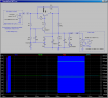
So I made the RB regulator in LTspice today, but it doesn't oscillate for some reason. :(

I made sure it was exactly like the diagram, with the right values, etc..., but it doesn't oscillate.

The zener voltage is 6.28
The power supply(Vi) voltage is 20
The output voltage(Vo) is 5.99
The current draw from the power supply is 2.9

And making a 100 ohm load doesn't do anything except drop Vo to about 2v

Any ideas?

-Ben
 
Introduce some noise. Pretend it's contact bounce from a switch. Many oscilators in simulators won't work because in the real world the noise that is inherent in the circuits isn't there.
 
Introduce some noise. Pretend it's contact bounce from a switch. Many oscilators in simulators won't work because in the real world the noise that is inherent in the circuits isn't there.

Oh wow that was fast, ok I will try that and see how it goes! :)

-Ben
 
Ok, I added some noise to it but it still doesn't seem to work! Where should I induce "noise" in the circuit?

-Ben
 
Sure it does.
 

Attachments

  • RB.png
    RB.png
    35.8 KB · Views: 583
  • RomanBlackSMPS.asc
    3.9 KB · Views: 325
I am not a pro at spice, but it sure would be useful :)

Wow Mike, is your circuit in spice more efficient than the original RB-smps?
There seems to be a lot of noise on the output.

.asc file--
 

Attachments

  • RomanBlackRegulator1.asc
    2.5 KB · Views: 304
Last edited:
I fixed your circuit. You had Q2 connected backwards.
 

Attachments

  • RomanBlackRegulator1[1].asc
    2.5 KB · Views: 335
I fixed your circuit. You had Q2 connected backwards.

Oh thanks, I didn't realize that the orientation matters!
I have been playing with Mikes RB-smps circuit and I have made a few changes to it
 

Attachments

  • RomanBlackRegulator1.asc
    4.8 KB · Views: 329
Last edited:
Arrggh! What on earth did you do to that beautiful little circuit Mike? :eek:
:D

Just use high gain transistors and it should work fine int he original form, they have been built on breadboards, PCBs, rats nested etc with good reliable results.

The whole point of the circuit is the simplicity and minimal parts count, which is why I am teasing Mike for adding heaps of parts. :)

Well I think that Mike's version still is not very complicated. ;)
Perhaps it could be more efficient too?

-Ben
 
Nope, looks like losses on R8 with 12v in and 5v out will be significant, and some losses on the R6-C3 snubber which I'm not even sure why it is there. :)

As for the simulator start up issue it's probably caused by the software not simulating the startup charge cycle properly. The SMPS starts up with the main switch transistor hard on, then once the output cap charges above the set point it switches off and the inductor field collapses causing a pretty hard overshoot on the first cycle and reliable starting is the result. Maybe if you can simulate "turning on the power" it should then sim ok. (Which seems to be what's happening in Mike's sim)
 
R8 was added to keep the LED lit without the switcher needing to run at all.
 
And I found that when barely loaded its output fluctuates a lot, with a LED indicator it is noticeable, so I use a 220ohm resistor to give the output some loading.

-Ben
 
BrownOut- Whoops sorry i missed that. :)

MikeML- Thanks I understand now. Your addition of R8 does lower efficiency a bit with low loads, at 50:50 duty and 12v input the resistor will have about 12.5v across it, total waste for 50% of the time. That's 87mW waste. With an SMPS output of 5v 100mA 500mW efficiency would drop from a best case of over 90% efficiency down to 81% efficiency just from losses in that one resistor!

Ben7- Yeah the regulator output gets chaotic at very low loads and can even go linear when under a couple of mA. You can see some weird frequency results on the charts on my web page. It's a good reliable regulator (for the low parts count) but it does like a little bit of load. I should say it won't fail regulaton even at very low loads, it will still maintain the correct output voltage, but the oscillation can get a little chaotic. Anything over about 4mA output current should be very stable oscillating.
 
roman black reg.

Hi, MrRB I've been working on the black reg. for my metal detector ,my input vdc is 8.4,and my output neededs to be between 6.7- 6.8 @.9 amps. I made the cirt. but I can not get 6.7 volts dc out. what do I need to do change??????? Thank You
 
MrRB what parts do I have to change to get an ouot put of 6.7 to 6.8 volts out with an input of 8.4 at 1amp. thank you
 
Status
Not open for further replies.

Latest threads

Back
Top