Electro Tech is an online community (with over 170,000 members) who enjoy talking about and building electronic circuits, projects and gadgets. To participate you need to register. Registration is free. Click here to register now.
Welcome to our site! Electro Tech is an online community (with over 170,000 members) who enjoy talking about and building electronic circuits, projects and gadgets. To participate you need to register. Registration is free. Click here to register now.
No, how can it?, you've added 3V DC to the original ac signal.
RMS is the heating value of the AC wave that equals the heating effect of the same value DC. So 3V DC would warm a resistor exactly the same as 3V RMS.
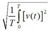
If you review the definition of root mean squared you'll see that level shifting a sinusoid will infact change it's RMS value. Nigel is correct, I just wanted to show the equation so it made sense. If you're like me you see things better in terms of equations. If you're not, then it may look like a mess
Probably the easiest way to visualise the amount of power is to draw it as a graph, and then colour the area of power - for a standard sinewave you need to colour both the positive and negative excursions. With a sinewave sat on a DC level, colour everything between the DC level and the sinewave (assuming the sinewave doesn't drop below zero).
thanks for reply
i know this fact i want to confire
clamper circuit shift the wave at some dc level whereas input has 0 dc level
then is it not violated the law of cinservation of energy?
what physically rms value of a signal means?
can we say that it is energy of a signal?
please explain :shock:
MAthematically, RMS is a rather more accurate way of average finding,
REgarding electricity, the RMS value of AC represents the value of DC that would be required to produce the same heating (energy transfer) as the AC whose RMS value u have calculated. A 312V AC would produce the heating effect of only 220V DC.
thanks for reply
i know this fact i want to confire
clamper circuit shift the wave at some dc level whereas input has 0 dc level
then is it not violated the law of cinservation of energy?
I explained it earlier, and fsahmed just has again. RMS is simply the AC value that gives the same heating effect as the same DC voltage. So if you'e got a light buld, 230V AC will give EXACTLY the same brightness as 230V DC - it doesn't matter what waveshape the AC is, that's the whole point of RMS.
MAthematically, RMS is a rather more accurate way of average finding,
REgarding electricity, the RMS value of AC represents the value of DC that would be required to produce the same heating (energy transfer) as the AC whose RMS value u have calculated. A 312V AC would produce the heating effect of only 220V DC.
Its not a more accurate way, its just a slightly different calculation. If I want to find the average of a set of numbers I'm certainly not going to use RMS. It is simply a tool to calculate (at least in terms of circuits) the effective DC voltage of a waveform. It is no more accurate or no less accurate than anything else. It is simply just the mean of the squared values, sometimes called the quadratic mean.
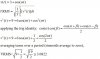
Styx is correct, in the terms of units Power (Watts) are in joules/sec. Once you integrate over all frequency or over a period (see Parseval's Theorem) you get a number that represents the energy in the signal. Parseval's Theorem just states that there is a conservation of energy between time domain and frequency domain.
Just look at the integral. Its the integral of the absolute value squared of the transfer function multiplied by the fourier transform of the input function integrated over all frequency.
Just look at the integral. Its the integral of the absolute value squared of the transfer function multiplied by the fourier transform of the input function integrated over all frequency.
Just look at the integral. Its the integral of the absolute value squared of the transfer function multiplied by the fourier transform of the input function integrated over all frequency.
It's probably easiest to visualise if you draw it out?.
Get a piece of graph paper, and draw a horizontal line across the middle (0V x-axis) - bear in mind, this now looks like a scope display!. Now draw a sine wave (or whatever wave you want) along the x-axis you just drew, going both above and below 0V. Next get a coloured pencil (or crayon) and fill it in, between the 0V line and the wave you drew, both above and below the 0V line - this will give you a series of coloured half-sine pulses, alternately positive and negative. This is the total amount of power contained in the signal.
Next, draw another sinewave, but this time DC shift it ABOVE the 0V line, so it doesn't cross 0V anywhere - then, as before, colour between the 0V line and the wave you drew (this time all the colour will be above the line). The coloured part again shows the amount of power in the signal.
In both cases (and all other ones) to measure the amount of power you need to calculate the surface area 'under the curve', which with graph paper can consist of counting the little squares :lol: Doing it electronically is FAR more complicated though, and requires 'true RMS' designs, which are essentially hardware multipliers.
This site uses cookies to help personalise content, tailor your experience and to keep you logged in if you register.
By continuing to use this site, you are consenting to our use of cookies.

")