Continue to Site

Welcome to our site!

Electro Tech is an online community (with over 170,000 members) who enjoy talking about and building electronic circuits, projects and gadgets. To participate you need to register. Registration is free. Click here to register now.

  • Welcome to our site! Electro Tech is an online community (with over 170,000 members) who enjoy talking about and building electronic circuits, projects and gadgets. To participate you need to register. Registration is free. Click here to register now.

RMK Trident 15 (15hp?) Rotary 3 phase Converter info required

Status
Not open for further replies.

Rotarymaker

New Member
Hi all,

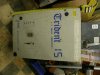
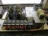
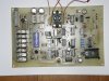
I have just picked up a Trident 15 single phase to 3 phase rotary converter cabinet box
It is the Mk 2 model.
It was made by RMK Components Ltd (in Belfast (UK) I think).
I think it is a 15hp rotary converter panel cabinet but not sure if it is 230V or 415V 3 phase output

I cannot find any info on this whatsoever .....I think this company has gone out of business years ago.
Perhaps someone out there is running this same unit in their garage / factory or farm? .... or has wired one of these units into place years ago?
If so, I need some simple info to start with......
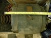
I do not have the idler (balancer) motor that came with this cabinet, can someone please inform me of what motor is best to use with this setup?
Is it a 240V or 415V motor?
What is the motors spec on its nameplate (hp? rpm? etc)?
Is it wired to this panel as star (Y symbol) or delta (triangle symbol)
Has anyone a service or user manual for this, that I may have a copy of?

really appreciate any help on this,
many thanks,
Rotarymaker.

7th July 2012 07:05 PM #16
OldLes OldLes is offline
Joined: Mar 2012
Location: Isle of Man - The isle separating UK and Ireland
Posts: 8
Send a message via Skype™ to OldLes

GEDW, I see it was March when I posted my question above, and since then I have analysed the circuits of a Transwave static convertor, a Transwave 10KW rotary, and a Boost 12 KW rotary. All 230 v single phase input, all incorporating a version of 230 to 415V step up auto transformer. The Boost has a simple one as described, the static has a "double" one (415-230-0-230-415) whilst the Transwave rotary has a 0-230-415, + 0-180 with a few extra tappings to allow probably for a 380v or a 415v output.
For you application, you would need a simple 0-230-415v autotransformer, BUT it would have to be rated at 25KVA, which would be capable of pulling 100 amps from your single phase supply. Is your supply big enough? You may need to contact your local electricity board regarding any special regulations or requirements.
How big an OUTPUT do you need? You could try to pick up a (say) 10 HP motor of otherwise similar specification, and reduce all you capacitors to one third of their current value. Typically in these rotaries and statics, if they need say 1,000 microfarads, they would use perhaps ten off 100 UFD in parallel, so you would simply remove six of them. If you follow this route, be sure to establish exactly the slave motor's specification. You may generally come across motors today which are marked up 230v delta connected, 415v star connected on the nameplate. Both the above mentioned convertors had 415v DELTA connected motors THESE ARE NOT THE SAME!!! Instead of 230/415v, they are really 415/720V, and all were two pole (2,940 rpm). The sort that would be used on a large fan with a star / delta startup configuration.
Since March, I have modified that UTube design I referred to, experimented with six different slave motors, and I THINK I am now at the stage where it WILL WORK!!!!
OldLes.

With ref above, to OldLes and anyone with such info ........
I've just found from todays forum search that you were involved in similar projects in the past
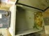
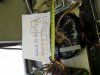
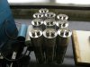
Any possibility of you sharing any of the info (schematics /circuits etc) on the Transwave rotarys as my RMK unit is possibly very similar .... it has, what looks like a large 3 wire toroidal stepup autotransformer on its 240V input??
Would really appreciate any comments / info.
PM me if you prefer.
thanks again for everyones time / help on this,
Rotarymaker

BTW OldLes, I'm not that far away from you .....just a canoe trip will take you here! :D ....to N.Ireland.
 
Last edited:
OK Rotary---. From your original post and that in TCM's thread, you machine sounds a bit like it is 230V input and 415v output, and utilises a step up transformer. Not unlike the two I studied previously (Transwave and Boost). Both of those used 2,900rpm slave motors, delta connected. Now if you stop and consider that carefully, you will see it is not a "typical modern" motor, but an old style motor as used on star / delta connected equipment. Probably you would need to source something from a big fan. (No way you start a 20HP fan, running at 2,900rpm direct on line at its rated voltage. I have a fairly modern Brook 7-1/2KW motor somewhere which is simply plated with something like this: "415v, delta connected, 7.5KW, 1,425rpm". It is (correction, WAS) only a three terminal motor, but I dug inside to reconnect it as a six terminal type. (I did consider using it with my Citringham 230/415v welder's primary as an auto transformer to build an RPC).
I don't know why these two RPC manufacturers used these motors, rather than similar HP motors of the more common 230/415v, but it seems that higher power motors are more likely to be this type.
The motor in the Boost RPC was labelled 440/480V, delta and 780/850V star.
One thing you must consider is the single phase start current, which is likely to peak at perhaps 100A. You need to be ready for upset neighbours, and irate supply company. Most of my reply to GEDW is probably similar to what I have just written.
If you PM me your email, I will send you copies of the two commercial units I mentioned above. I THINK I have got the circuit for the 4KW Transwave correctly transcribed, but in the case of the Boost, part of the circuit is in a little sealed black box, so it is NOT a working circuit. I don't feel it is fair to publish these online (manufacturers do have legal rights, and I don't want to end up in court) and so you must assure me they are for your personal study purposes and will not be published.
OldLes
 
Hi OldLes,
Really appreciate you taking time to reply, thanks.

I stripped out the autotransformer (after carefully noting it's wiring) and wired it to my 230V supply......exactly 415V output I'm getting from the "third top leg" which is good news.... at least it's still working as should be! There are also 3 separate isolated smaller (voltage and current wise) windings wound within this transformer outputing approx 24Vac....fed to the main control panel.
Overall, it's such a beast of an auto transformer, my domestic 32amp mcb started to "moan" and trip out on the constant on/off switching of this inductive load, even though no load was yet applied......I guess that'll certainly rule out using these for input current protection..... back to the good old bussman fuses, or plague my supplier for class c/d rated mcbs! .....Its hard to beat old school electrics ..... they were made to last (and work forever!) in them days!

I took a chance about 1 month ago and bought a very old 12.5hp Brookes motor.....it is one big heavy mother of a motor.....solid cast iron frame....it took 4 men to lift it out of the rear of my mpv.....with nipped fingers and holding backs all round! It has 6 wire connection (marked only for Delta 380/400V, 17.5amps, 1440rpm).....so I'm guessing it would originally have been started using a mechanical Star/Delta switchbox (to save neighbours complaining about dipping lights/supplies upon startup!) ...... it came off an old massive cast-iron bench circular wood saw that another guy bought to convert to be driven from a tractor PTO shaft.

See attachments for some pics of converter box in stripped down, original dirty state, condition.
As you may see from the bottom of the empty box, a few caps had reached their sell by date and leaked their vegetable oil guts, plus there was one wire from the cap bank that had chaffed thru on sharp edged metal frame probably also adding to their demise. These will all be replaced with new ones I have obtained from China.

Two sides of two of the contactors were reading high resistance, but I was able to switch over unused contacts on two of the other contactors to cheaply cure this problem...... again, the old gear lends itself to be easily disassembled / repaired!

As you can see, I've traced out the main heavy wiring from all the contactors ..... the control pcb with multiple chips and double side print will certainly take longer to achieve a usable schematic from...... a pain in the butt to do, but not impossible, since there's no surface mount electronics to drive you raving mad whilst loosing you eyesight!.

that's as far as I've got, so far,
Rotarymaker.

PS I've sent you a PM, regarding your kind offer, thanks.
 

Attachments

  • Trident 15 cabinet.JPG
    Trident 15 cabinet.JPG
    2.5 MB · Views: 786
  • Cap guts and mouse poo.JPG
    Cap guts and mouse poo.JPG
    2.8 MB · Views: 580
  • Autotransformer.JPG
    Autotransformer.JPG
    2.6 MB · Views: 649
  • Brookes 12.5hp motor.JPG
    Brookes 12.5hp motor.JPG
    2.6 MB · Views: 620
  • Main switchgear and cap bank.JPG
    Main switchgear and cap bank.JPG
    2.3 MB · Views: 816
  • New cap bank.JPG
    New cap bank.JPG
    2.7 MB · Views: 730
  • Control board.JPG
    Control board.JPG
    3.1 MB · Views: 690
These were the BEST you could buy! I remember seeing these in action over in The Republic the Mk3 as far as I recall which you have was more a light domestic unit similar to Transwave but a whole lot more reliable than the mass-produced converters. They were about profit than reliability RMK appeared to come from the opposite direction, they were a 12,000 euro price so you got what you paid for. There was a guy by the name of Robin who was an expert in this field he had immense knowledge of power conversion realities.

The last I heard RMK secured a deal with the national water board over there and that's when this company seemed to take off in the corporate market they were designing a TRIDENT MK5 powerhouse at the time that would run continuously in remote pumping stations it used proprietary monitoring electronics and the most expensive switchgear running multiple pump motors of 30hp continuously and could report faults back to base remotely.

That's when they really hit the jackpot and I'm sure they were bought out by one of their big customers. No one after that produced a converter so robust so I'm sure they purchased copyrights and patents along with everything else.

If you still have the MK3 keep hold of it. If anyone has a MK5 please contact me as I've been on the lookout for one for a long time.
 
Last edited:
Status
Not open for further replies.

Latest threads

New Articles From Microcontroller Tips

Back
Top