Continue to Site

Welcome to our site!

Electro Tech is an online community (with over 170,000 members) who enjoy talking about and building electronic circuits, projects and gadgets. To participate you need to register. Registration is free. Click here to register now.

  • Welcome to our site! Electro Tech is an online community (with over 170,000 members) who enjoy talking about and building electronic circuits, projects and gadgets. To participate you need to register. Registration is free. Click here to register now.

rise and fall time

Status
Not open for further replies.

mstechca

New Member
Here's the astable multivibrator I used in my circuit, but my capacitors are 0.1uF ceramic and I use 2K for the 1K, and I used 27K for the 15K.

**broken link removed**

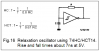
How do I determine the rise time and the fall time of this circuit?

My datasheet for my uC states that 20ns is the maximum rise time and 20ns is the maximum fall time. I think this may be why it isn't starting properly.
 
The rise times will be really slow. The 0.1uF cap has to charge through the 2k load resistor and the base of the other transistor (a diode junction), giving you a time constant of 200 usec, or a 10%-90% risetime of 440 usec.
The fall times will be much faster, and will be dependent on the trannies you use.
 
1/6 of a 74HC14 hex Schmitt inverter package makes an oscillator with only 7ns rise and fall times. They are so quick that I can't see them on my 'scope. :lol:
 

Attachments

  • 74hc14_oscillator.png
    74hc14_oscillator.png
    9.1 KB · Views: 911
I don't have a 74HC14.
 
Digikey.ca has sold out of their Texas Instruments SN74HC14 for $.60CAN, but have the same thing in stock from ST Micro for $.72CAN.
Of course Digikey has a minimum order amount you must meet and you have to pay a few bucks for the courier. So order lots more stuff. :lol:
 
When I changed the collector resistors to 100 ohms and the base resistors to 27K and made the capacitors 100pF, I generated radio interference :(

Is there another circuit I can use with transistors that does not transmit interference?
 
Each 100pF cap discharges into its 27k resistor in 2us. Therefore the oscillator's frequency is about 250kHz. The output is a square-wave with strong odd harmonics. The strongest is the 3rd harmonic at about 1000kHz in the middle of the AM radio band. Other odd harmonics will have frequencies much higher.

Any square-wave oscillator at that high frequency will generate radio interference. Put it in a grounded metal box to shield it, or use very short wires (a pcb). :lol:
 
mstechca said:
When I changed the collector resistors to 100 ohms and the base resistors to 27K and made the capacitors 100pF, I generated radio interference :(

Is there another circuit I can use with transistors that does not transmit interference?
What frequency are you shooting for? What transistors do you have on hand?
 
I'm trying to make an external oscillator which satisfies the AT89C2051 uC chip. But it requires a frequency < 24Mhz and a maximum rise time of 20ns and a maximum fall time of 20ns, and the value (0 or 1) must stay in one state for at least 15ns.

I think maybe there is a misrepresentation in ATMEL's docs.
 
I have to make the oscillator which meets the requirements outlined below. I don't have access to crystals at this time.
 

Attachments

  • clk_166.gif
    clk_166.gif
    6.9 KB · Views: 732
Prepackaged oscillators are the way to go. Feed 'em power and ground, they spit out your nice square wave at frequency with good rise and fall characteristics. In DIP form, they usually have normal 14-pin package size or can be had in smaller versions. They'll take up less space than a discrete circuit made of components in the same form (thru-hole or SMT). They'll usually be cheaper than buying the discrete components to make an oscillator.

The disadvantage is that if you're wanting to goof around with the frequency, swapping out components on the discrete version is handier.

Dean
 
Status
Not open for further replies.

Latest threads

Back
Top