Continue to Site

Welcome to our site!

Electro Tech is an online community (with over 170,000 members) who enjoy talking about and building electronic circuits, projects and gadgets. To participate you need to register. Registration is free. Click here to register now.

  • Welcome to our site! Electro Tech is an online community (with over 170,000 members) who enjoy talking about and building electronic circuits, projects and gadgets. To participate you need to register. Registration is free. Click here to register now.

RF receiver

Status
Not open for further replies.

magnumpi67

New Member
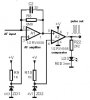
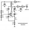
can someone tell me how this thing works. If the web address won't open, do a copy and paste on the address bar. I also need to break the circuit down into different blocks. The circuit is at: **broken link removed**. scroll down to page 15. it's in pdf format.
 
Looking at the schematic-T1, A1 and A2 are the receiver. From the specifications I would say that the receiver receives a series of pulses from the transmitter and depending upon the code it activates relay 1 or 2.
Do you have some more specific questions?
 
The decoder part is simply, just read the datasheet.(two decoders with different setup codes.)
The receiver part also a most common solution:
 

Attachments

  • ampcomp.JPG
    ampcomp.JPG
    20.6 KB · Views: 923
  • supreg.JPG
    supreg.JPG
    23.8 KB · Views: 946
The flip-flops are to keep the relays energized for a period of time depending upon the programing.
 
Looking at the schematic for the superregenerative receiver, I know R1 and C4 acts as a noise filter, R4 and R5 together is a voltage divider that provides proper biasing at the base of the transistor. I can't firgure out what C8 and L1 do and also C3 and L2. CV1 is a tuning capacitor. I know the signal goes through R6. What about R2, is it part of the noise filter?
 
Status
Not open for further replies.

New Articles From Microcontroller Tips

Back
Top