Continue to Site

Welcome to our site!

Electro Tech is an online community (with over 170,000 members) who enjoy talking about and building electronic circuits, projects and gadgets. To participate you need to register. Registration is free. Click here to register now.

  • Welcome to our site! Electro Tech is an online community (with over 170,000 members) who enjoy talking about and building electronic circuits, projects and gadgets. To participate you need to register. Registration is free. Click here to register now.

RF Power Amp (Share)

Status
Not open for further replies.
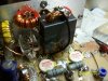
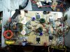
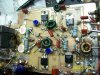
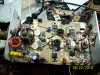
I really appreciate you all's help. I pulled the resistor and got about 8 watts right off. Then I was looking at the output network which you see I'm using a T network and something didn't look right so I changed it and I'm at 15 to 20 watts. One you get here they start popping up exponentially but that resistor was holding me back. You guys were right on. I wonder is those two 33 ohms resistors are killing my base current? It's so hard to adjust with only 10 ohms because one each transistor turns on the load changes on the LM317's. I'm slowly bumping up the driver's biasing too. I'm sorta concerned with heat so might run it shy of full 200. The broadband characteristics are pretty good. Through a frequency span of 2.5MHz under PLL control it jumps 15 to 20 watts right now. Probably the output network.
 
You might want to probe around for some unwanted oscillations. Something might be unstable.
 
Last edited:
Well, I have it set up class A. Actually you establish it by the Idc of the transistors. That is the standing base current. But I can actually use the voltage and set to where it just turns on, on both. You can also put a scope on it. If I turn both off then turn one on I can actually see pulsating DC at the output. If I turn it higher than one side will amplify the whole signal but you will have less voltage than running both. So if you use the scope you can adjust to where you see pulsating DC from one then lowly turn on the other and you will have a large voltage amplitude at the output. Then just peak them both. If you have one set up to amplify more than half the signal you will get a lower output.

i have edited ur design for more saving components
 

Attachments

  • Push-Pull2.GIF
    Push-Pull2.GIF
    18 KB · Views: 159
Last edited:
You might want to probe around for some unwanted oscillations. Something might be unstable.

Good call. I already did that 2 days ago and found one in the frequency control box so a rearranged the whole output string ending up with a 1 watt output transistor (MRF473) in it. But I finished it finally. The dummy load I was using was throwing off my power/SWR readings. I put it on antenna and saw 220 watts on one frequency. Supposed to be 200. It almost fried a 300 watt dummy load. It took over an hour to cool down. So it's working. Let me see what this guy did with the schematic. Should be interesting.
 
Last edited:
i have edited ur design for more saving components

It's OK but you left out the other driver. I will do a final update once I button it up. I got to mount the fan and other stuff. I bumped up the bias on the drivers so those resistors changed which forced me to change the emitter resistor power ratings. The 1/4 watts fried fast. That was stupid anyway. Don't know what I was thinking. So I better send new pictures too.
 
i have edited ur design for more saving components
Nice try, but L6 now connects the two bias supplies and short circuits them both to ground.

You have removed the values for R8, R9, and R12 so the bias is unknown. Even if the bias is correct Q2 will probably be much worse with second harmonics (which is why a lot of linear amps are push pull).

You took out the Vcc filter at L7.
 
Last edited:
Nice try, but L6 now connects the two bias supplies and short circuits them both to ground.
i have edited it again.

You have removed the values for R8, R9, and R12 so the bias is unknown. Even if the bias is correct Q2 will probably be much worse with second harmonics (which is why a lot of linear amps are push pull).

You took out the Vcc filter at L7
u r right becauze this is large signal. Class A using in this case is uncomfortable. using transformer directly is good for quanlity.
 

Attachments

  • Push-Pull3.GIF
    Push-Pull3.GIF
    16.2 KB · Views: 147
I think he is toying with me. Here, this is the final design. Not much changed, just that resistor and I raised the current on the driver's base and changed some transformers you can see in the pictures. Oh, and a missing filter cap that was all the way in lower left corner. It removed itself in my face. I should have checked the voltage on it.
 

Attachments

  • Push-Pull.gif
    Push-Pull.gif
    19.2 KB · Views: 163
  • 100_1551.JPG
    100_1551.JPG
    324.3 KB · Views: 151
  • 100_1550.JPG
    100_1550.JPG
    301.1 KB · Views: 135
  • 100_1553.JPG
    100_1553.JPG
    310 KB · Views: 137
  • 100_1549.JPG
    100_1549.JPG
    300.3 KB · Views: 148
  • 100_1552.JPG
    100_1552.JPG
    309.9 KB · Views: 144
  • Push-Pull.gif
    Push-Pull.gif
    19.6 KB · Views: 147
Last edited:
I think he is toying with me. Here, this is the final design. Not much changed, just that resistor and I raised the current on the driver's base and changed some transformers you can see in the pictures. Oh, and a missing filter cap that was all the way in lower left corner. It removed itself in my face. I should have checked the voltage on it.
i don't toy u. how ur design operate? how related linear is and how to determine? i just want to discuss about
problem of the circuit. like i said before, using transformer dirtly is good for performance
 
i don't toy u. how ur design operate? how related linear is and how to determine? i just want to discuss about
problem of the circuit. like i said before, using transformer dirtly is good for performance
Do you understand that this amplifier is for transmitting on HF bands? It is not the same as audio. Tell us about your RF power amplifier experience.
can u please post about principles of "cutting angle" compose of A,AB,B, C,D,E. then to compare.
There is not enough room here to teach you basic RF design. Fortunately there are places you can learn. If you speak English, I would suggest the ARRL Handbook for Radio Communications, or the RSGB Radio Communication Handbook. They may be available in other languages.
 
Do you understand that this amplifier is for transmitting on HF bands? It is not the same as audio. Tell us about your RF power amplifier experience.
There is not enough room here to teach you basic RF design. Fortunately there are places you can learn. If you speak English, I would suggest the ARRL Handbook for Radio Communications, or the RSGB Radio Communication Handbook. They may be available in other languages.
i have no much experience in RF amplifier and maybe my english is not well (sure)...so that is reason i join this forum. I just say the things i know. So, i also discuss the things i concern. i just want to understand clear about this circuit.
 
Status
Not open for further replies.

New Articles From Microcontroller Tips

Back
Top