Continue to Site

Welcome to our site!

Electro Tech is an online community (with over 170,000 members) who enjoy talking about and building electronic circuits, projects and gadgets. To participate you need to register. Registration is free. Click here to register now.

  • Welcome to our site! Electro Tech is an online community (with over 170,000 members) who enjoy talking about and building electronic circuits, projects and gadgets. To participate you need to register. Registration is free. Click here to register now.

revisiting an old project = caculator

Status
Not open for further replies.

MrDEB

Well-Known Member
I started this project several years ago and decided to redesign it with a better design
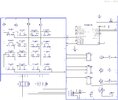
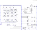
Orginally used an LCD but the LCD is at the size limit of the enclosure width so seeing how I only need a maxium of three digits decided to go with 3-7 segment led digits.
Has 16 tactil buttons but really only need 14.
The displays are Common Cathode. Waiting for delivery of displays before going any futher but here is the schematic.
Contemplated not using the KEYBOARD16.BAS but why make life harder?
The mosfit is for battery reverse protection
 

Attachments

  • dom 2022.jpg
    dom 2022.jpg
    432.5 KB · Views: 218
I find your schematics very hard to follow but if I read it right, you don't have your segments or key columns connected to your pic.

Mike.
 
+1, Mike

I'm not sure what use a three-digit calculator has (especially since it has no dec point), but:

- no connections to the columns of the 4x4 keypad, so you can't read which button is pressed
- no connection to the G segment of the 7-segment displays, so you can't display numbers
- missing tons of connections to the uC
- the 18F2221 was ancient 10 years ago
 
OUPS! I forgot to connect the segments to the pic. the rows are connected to portb0-3
Sorry about hard to follow schematic but I found using a BUS for connections easier but am contemplating trying a different method.
 
just saw Tumbleweeds post.
this is a dominio caculator for playing MEXICAN TRAIN. Have been caught with lots of dominios at the end of each round so lots to dots to count. Will make additions as needed.
As for the 18f2221, I have about 20 of them from several designs as well as 20 18f43k22's
 
Is this easier to follow? I edited some of the bus connectors so just NET NAME is displayed.
Added missing connections. Should us the BUS for Vcc and GRD connections only?
 

Attachments

  • dom 2022.jpg
    dom 2022.jpg
    446.7 KB · Views: 209
Normally a bus is used for "like" connections... things that go to the same place/function.
You might have a bus for the keypad, a bus for the display, etc. You just connect everything to one bus, so it serves no real purpose.

If you put the columns on PORTB you can use the internal pullups and get rid of the 10K resistors.

Add the connection to MCLR (I still don't believe your schematic software lets you get away with this... doesn't it complain about missing connections??).
 
AH yes ol eagle eye, no connection to mclr.
Plan to do suggested revisions
Thanks
 
Your "schematic" is certainly unique, and next to useless. A schematic is supposed to show connections - you might as well just label the pins and delete all the lines for all the good your picture is,

But anyway, the symbol for tact switches is terrible. This picture shows the wiring of a 4 pin switch, Terminals 1 & 2 are connected together, as are terminals 3 & 4. When the switch is pressed, 1 & 2 are connected to 3 & 4. Based on your schematic symbol, it appears that you'll connect pin 1 and pin 2....which are already connected, meaning your switches will do nothing. Maybe the schematic symbol is a really poor representation, or you have all the switches mis-wired. Verify reality between a switch, the schematic symbol and the pcb footprint.

6mm switch schemtic'.png
 
I am using the symbol from Diptrace. Tumbleweed mentioned in a different thread about the tactile switch symbol.
Have used posted symbol in numerious projects as well as PCBoards with no issues but yes I will change the tactle switch symbol. The symbol that is in post #9 is not a tactil switch.
 
The symbol that is in post #9 is not a tactil switch.

Really? Omron seems to think it is, or at least that's the schematic of what's actually inside the switch.... which is the important part as far as knowing what the connections should be. Excuse me for interrupting; you apparently have this under control.

omron B3F.png
 
Me? Just a guy trying to help since it appears you need it. Apparently, I was mistaken.
 
here is a screen shot of the tactil switch in Diptrace.
 

Attachments

  • Screenshot (85).png
    Screenshot (85).png
    208.1 KB · Views: 203
The problem is that your schematic appears to show your switches shorted out.
ts.png


Mike.
 
The picture below shows the Dip Trace switch pattern on the left. Clarifying it just a bit, the center picture is what this pattern is showing (my apologies for flipping it 180). What the symbol shows is that pins 1 and 2 (or 3 & 4 if flipped 180) get shorted together when the button is pressed. But this accomplishes nothing, because pins 1 and 2 are internally connected together inside the switch. If you believe the symbol, you think 1 and 2 will be connected when the button is pressed, but in fact, they are always connected, and if you wire the switch this way, it will always read as pressed.

The right hand symbol actually shows what's going on clearly. 1 & 2 are connected together inside the switch. 3 & 4 are connected together inside the switch. When the button is pressed, 1 & 2 are connected to 3 & 4. Glance at the symbol, and everything is revealed.

I have made the mistake of laying out a board with incorrect switch connections. With a little effort, you can sort of fix the mistake by rotating the switch 90 degrees and bending the pins to fit but it's a mess in the end. It's so much better when the symbol is clear and concise so it's hard to make a mistake!

I don't think there's anything further to add here.

BTW, Mrdeb's switch, copied from what he calls a schematic, is only connected to one point in the circuit, so for that switch, it's not going to work anyway.

Switch Symbol Comparison.png
 
I like your CORRECT SYMBOL
thinking of redoing my switches? after I figure out the EASYEDA program.
 
Status
Not open for further replies.

Latest threads

New Articles From Microcontroller Tips

Back
Top