Continue to Site

Welcome to our site!

Electro Tech is an online community (with over 170,000 members) who enjoy talking about and building electronic circuits, projects and gadgets. To participate you need to register. Registration is free. Click here to register now.

  • Welcome to our site! Electro Tech is an online community (with over 170,000 members) who enjoy talking about and building electronic circuits, projects and gadgets. To participate you need to register. Registration is free. Click here to register now.

Revised Knight Rider Circuit to 32 LED's using Logic IC

Status
Not open for further replies.

Miss_B_Haven

New Member
Hi,
I tried to revise Knight Rider circuit to have 32 LED's using 2 of 74HC193, NAND gate, 4-16 decoder, and Timer 555. However; I'm experiencing some unexpected results from my design. I need your opinion on how to fix my design to have correct sequence of lighting LED1 to LED32 and then LED31 to LED1 (back and forth forever).

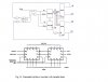
Per attached schematic Senario_1, the outcome sequence as: LED1 lights up and increments “counter up” up to LED32. Then, LED16 lights up and “counter down” decrements down to LED1. After that, counter down loops around LED16 and LED1 forever.

In the Senario_2 schematic, the outcome sequence as: LED1 lights up and increments “counter up” up to LED32. Then, LED31 lights up and “counter down” decrements to LED17. After that, counter down loops around LED31 to LED17 forever.

Please advise. Thanks in advance.
 

Attachments

  • Senario_1.pdf
    21.7 KB · Views: 683
  • Senario_2.pdf
    33.3 KB · Views: 538
you have connected borrow & carry of IC1 to 2nd IC up/down, you have to use borrow and carry in a manner to switch the ICs and switch the input to up/down. i will try to post you the way it could be fixed, if you couldnt resolve it.

Edit: i didnt go through the datasheet of the ocunter yet, you will may have to use load input to enable it using carry / borrow
 
Last edited:
Actually the Carry of the first chip should go to the Count Up of the second and the Borrow of the first should go to the Count Down of the second chip. That is correct for cascading that chip.

There is an older version of the circuit on this page. You may want to note how the old 7400 quad nand is configured and make sure you are configured the same for your chip. That is the determing factor in the Up/Down count.

Ron
 
reloadron

as i understand the case is different here, the DEMUX is used separately for each counters, cascading it in that way will not give right knight rider out for 32 LEDs, some extra circuitry is required to get it done.
 
Ah, I see your point. I was looking at cascading as shown in this application note. I wasn't thinking the effect as in Knight Rider. I wrongly assumed you would simply cascade and set it up as in my link. However, the second chip added a caveat. My bad on that note. Not sure how to get beyond the 16 original lamps.

Ron
 
see the attached schematic, it may work as you require. both counters are cascaded and then the decoder is switched via the 2nd counter when its 0bit goes high. to make the system count up and down feed back from decoder stage is taken to set and reset (enable & disable) clock input to up/down inputs.

hope it will work fine
 

Attachments

  • knight rider 32 lights.JPG
    knight rider 32 lights.JPG
    63.8 KB · Views: 1,135
I took mbarazeen’s advices and revised my circuit. The result is only LED1 lights up …permanently. I mean it’s always on even I disconnected it from the NAND gate chip. I may miss the connection somewhere in the circuit.:eek:
 

Attachments

  • Senario_3.pdf
    396.3 KB · Views: 447
I took mbarazeen’s advices and revised my circuit. The result is only LED1 lights up …permanently. I mean it’s always on even I disconnected it from the NAND gate chip. I may miss the connection somewhere in the circuit.:eek:

you have made a mistake in the connection, also the circuit i posted indicates up/down connection for both counters, but in real both are cascaded and only the 1st counter will be connected to up/down AND gate outputs. you have wired the clear (reset) input of both counters together & to down count of 1st IC its wront too.


so connect both ICs as you have connected in your circuit "Senario_1.pdf" for cascading. take only the up/down of the 1st IC to connect it to AND gates
 
Pcb

May be i'm out of mind a little bit more to understand about this scheme, but actually i really need the PCB scheme to complete this project..may be you can help me... so, this subject can be real, not just as a theoretical on sheet..
I really love this project if i can make it true... thank you so much..
Rahayu Kanaya > Denpasar - Bali, Indonesia
 
Status
Not open for further replies.

Latest threads

New Articles From Microcontroller Tips

Back
Top