Continue to Site

Welcome to our site!

Electro Tech is an online community (with over 170,000 members) who enjoy talking about and building electronic circuits, projects and gadgets. To participate you need to register. Registration is free. Click here to register now.

  • Welcome to our site! Electro Tech is an online community (with over 170,000 members) who enjoy talking about and building electronic circuits, projects and gadgets. To participate you need to register. Registration is free. Click here to register now.

Reverse polarity 12v DC automotive use

Status
Not open for further replies.

capofarukgb

New Member
Good evenings, it's probably very easy but I can not get my head around it, I am trying to mimic what is normally achieved through a mechanical Relay, reversing a trigger polarity from hot 12v + to negative ground.
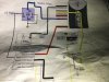
Currently achieved this by using as said before spdt mechanical relay 12v 2amp, 86 + 12v trigger, 30 and 85 ground negative 87 is my negative output.
Excellent job done !! Not really, Im not a fan of mechanical relays, and want to change to solid state type, SSR are expensive, so since what I am trying achieve is simple, I wonder any of you have another method using ICs or etc, as long it's cheap and smaller than normal hella relay.
The image is what I have installed
Thanks in advance guys
 

Attachments

  • image.jpeg
    image.jpeg
    1.3 MB · Views: 175
use this
upload_2016-1-19_11-43-2.png
 
Last edited:
Yes, 12V is +ve. The earth symbol is the chassis/negative. I'm not sure of the current requirement of the trigger input of the PDM60, but I'm assuming it's quite small, therefore a small signal transistor e.g. BC548, 2N2222, etc. should be acceptable. The diode can be 1N4148, and is likely optional (only required if PDM60 input is internally a relay coil). I've updated the schematic to reflect these details.
 
Yes, 12V is +ve. The earth symbol is the chassis/negative. I'm not sure of the current requirement of the trigger input of the PDM60, but I'm assuming it's quite small, therefore a small signal transistor e.g. BC548, 2N2222, etc. should be acceptable. The diode can be 1N4148, and is likely optional (only required if PDM60 input is internally a relay coil). I've updated the schematic to reflect these details.
Thanks buddy the PDM 60 actually only requires a negative ground tigger on the BLUE wire the relay actually doesn't have any other connection to the PDM, I take it the OUT from the collector can go straight to the blue wire ? And this would be a negative ground when the circuit is active ? Thanks again
 
I was saying that I don't know what is inside the PDM60, e.g. it could have a relay inside that connects to the blue wire. I think it's unlikely though.

Yes, the circuit will output a "ground" (or close to) signal when you input a voltage >~6V. The output connects to the blue wire.
 
Status
Not open for further replies.

New Articles From Microcontroller Tips

Back
Top