Hello guys,
Recently I decided to start learning how to design almost simple circuits.
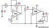
Today I came across to an idea, I decided to put the ready circuits here in this thread and kindly ask the engineers and the experts in the field to come and tell for instance why a component is there at that segment of a circuit and especially why the designer has chosen that value for it (the formulas behind it). Most of times I know why a particular component is there in a particular circuit but do not know why the designer has chosen that value for it.
Here we suppose that we have all stuff to design and analysis the circuits (i.e. Scop, function generator and multi meter).
The main purpose of this thread is to improve our knowledge of designing and analysis the circuits.
I kindly demand experts Nigel, Audioguru, Ron.H, MrAl, and all expert engineer to help.
Thanks.
Zesla
Recently I decided to start learning how to design almost simple circuits.
Today I came across to an idea, I decided to put the ready circuits here in this thread and kindly ask the engineers and the experts in the field to come and tell for instance why a component is there at that segment of a circuit and especially why the designer has chosen that value for it (the formulas behind it). Most of times I know why a particular component is there in a particular circuit but do not know why the designer has chosen that value for it.
Here we suppose that we have all stuff to design and analysis the circuits (i.e. Scop, function generator and multi meter).
The main purpose of this thread is to improve our knowledge of designing and analysis the circuits.
I kindly demand experts Nigel, Audioguru, Ron.H, MrAl, and all expert engineer to help.
Thanks.
Zesla