Continue to Site

Welcome to our site!

Electro Tech is an online community (with over 170,000 members) who enjoy talking about and building electronic circuits, projects and gadgets. To participate you need to register. Registration is free. Click here to register now.

  • Welcome to our site! Electro Tech is an online community (with over 170,000 members) who enjoy talking about and building electronic circuits, projects and gadgets. To participate you need to register. Registration is free. Click here to register now.

Retake GW-GFG8020 Function generator

Status
Not open for further replies.

fezder

Well-Known Member
Ok, so it would have been necroing the old thread, but now as i have somewhat more knowledge, i decided to retake this repairing issue. And, there have been couple improvements/advancements:

https://www.electro-tech-online.com...ction-generator-gw-goodwill-gfg-8020g.138686/
^Old thread

So, i found that component that caused malfunction in -5 power rail, it was very interesting find, but at pepper suggested, i searched for s/c's in power rails, and this U402 (dual line receiver, 75107) was culprit, it had internal short and i replaced it, now power rails are working (hooray!)

i also changed couple more components which didn't work as intended, so now voltage rails are ok AND there is signal as well as frequency counter works (correction, not always counter work).
however, there is something fishy still in this issue:
sinewave is by default settings all the time negative, but it can be corrected with dc-offset knob. duty-cycle affects only positive-half, not negative. When negative setting is tried, positive is effected.

triangle wave is centered as should be, but still duty-cycle won't effect negative cycle.

Square wave has all functions covered , duty cycle effects both halves.
If you guys have any tips, i'll glady hear it out, this is now much closer to be fully repaired unit now
here's the manual, well explained how this unit works and stuff....but sadly, couldn't find schematics
https://www.ece.rice.edu/~jdw/data_sheets/gfg8020h.pdf
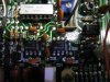
full circuit
Format FactoryIMG_1053.jpg
changed ic's U303 (7404) and U304 (4081)
correction, originals work also...
Format FactoryIMG_1054.jpg
and positive/negative constant current sections, as well as VCF control (rightmost '741) and changed ic that had short inside, U301 (75107)
 

Attachments

  • Format FactoryIMG_1055.jpg
    Format FactoryIMG_1055.jpg
    1.4 MB · Views: 501
Last edited:
Ok, amplitudes etc are now in order, calibrated it with trimmers
Only frequency counter left now to get working
 
right, managed to partially repair counter, it shows now when gate time is 0.1s, but no lower like 1s. IC that takes care of 7-segment driving, latches well like supposed in 0.1s region, but no latching in 1s, so it holds last value from 0.1s gate time
 
counter is now working, now only duty setting to work in negative and cmos-square has 0.6-0.4v positive offset, could be from some semiconductor, although i checked each semiconductors out-circuit.
only line driver 75107, which was earlier AN-suffix (plastic case) is now AJ-suffix (ceramic) and ca3046 transistor array are what measure differ from working units.
Then again, i can live without TTl/cmos output and fully-adjustable duty on other unit
 
Sounds like some success.

Theres a possibilty the 0.6v offset on square is normal, a diode drop above ground can be tolerated on most ic's.

Could you post a pic of the triangle wave at a couple of diffrent duty settings?, I dont know what you mean by duty, that normally applies to square waves, it sounds like maybe your machine has a control that enables you to control linearity of the triangle, maybe so you can make sawtooth waveforms.
 
Sorry, forgot to mention couple relevant things, thanks for asking:
on working unit i have, there is no dc-offset at all on TTL/CMOS. Yeah, 0.6v is considered as ground still at ic's input, so it could be ignored

Then, the duty cycle, it effects only square for both positive/negative portion, but only positive/rising for triangle/sine, so it can be used to create sawtooth or slow-rise sine. THIS is how it behaved in working unit.

Now on faulty, sine/triangle work as in working one, but in square, only positive portion is affected.
Couple more observations: duty affects TTL's only negative, while CMOS's only positive
i've checked all semiconductos and none busted were found. There seems to be short/leackage somewhere in circuit as i measured connector that is related close to amplifier section, working one has several megs of resistance, where faulty has only 870 ohms!

also, base of amplfier start-transistors, as well as diodes at the end of it won't show change in postive portion of signal, only negative, where in working one changes both portions.
Also, lower of those bigger transistors on right get very hot after while, something cooks it. But they get hottish in wokring one too. Tested those transistors and they tested ok
there were also difference betwen upper-lower at leftmost two transistor bases measured to ground, lower ones measured as 780 ohms from working, faulty had 220 ohms
IMG_1056marked~1.jpg IMG_1056.jpg
 
Hmm,

My next move would be to check the esr of all the electrolytics.

0.6v bias, maybe a fault on the o/p protection circuit, possibly someone applied a voltage to the o/p.
 
hmm, good point, i never thought checking ESR as this isn't SMPS stuff.
I think too that ouput pin has seen voltage as output resistors (2x 47 ohm) were burnt at TTL/CMOS. Theyre replaced but that won't tell of course if there are something else looming, most likely there is
 
well, now that you mentioned it, worth a shot, i tried looking via google but surprise, no avail. But, i'll try and send email to 'em
 
contacted gw and got reply where they say local branch will contact me next monday. I measured ESR's of all main caps , none alarming but i changed to as they were bit lighter than expected. Didn't help issues though, but those transistors are now just bit cooler so caps seemed to have small effect.
 
OK, i got contacted from GW and they'll request schematics. They had their thoughts as this is quite old, but they try, which is enough for me!
 
I got schemtaics from GW, but i don't post them unless i have permission to do so, would hate any hassle. But, i did notice there is +-22v rail that i'm about to check, didn't notice that earlier (oops!)
 
well of course +-22 volts rail was ok because it feeded other lines, but now it's checked and confirmed as working
 
so, issues now:
cmos has offset of +0.2volts to 0.5 volts when cmos is selected, depending on output amplitude (lower amplitude has more offset, at full amplitude lower, so offset changes inverted-fashion; amplitude up->offset down). When TTL is selected, offset changes to +0.32 volts solid

other more severe is that only negative portion of duty cycle is effected
 
cmos has offset of +0.2volts to 0.5 volts when cmos is selected, depending on output amplitude (lower amplitude has more offset, at full amplitude lower, so offset changes inverted-fashion; amplitude up->offset down). When TTL is selected, offset changes to +0.32 volts solid

That problem might be partially between the instrument and the chair. You don't have control of offsets with TTL or CMOS. VR302 will set the max output in CMOS mode. If U303 (CD4081) https://www.futurlec.com/4000Series/CD4081.shtml is degraded, that could affect CMOS offset. You could check it at pin #11 or #2 of U303.

The offset TTL seems fine. TTL meant 5V when it was invented. You won't find 3V3 TTL.

other more severe is that only negative portion of duty cycle is effected

You need to better explain. The CMOS offset isn't low enough. It should not be adjustable. Points to U303, but check pins (11 or 2)
 
Last edited:
This offset i mean at CMOS output (taken from output jack)
pin 11 shows only 80mv offset, much lower value than this
NewFile3-edited.png
You need to better explain
I mean duty cycle for PWM values for square wave (shot taken from square wave output, not from TTL/CMOS)
NewFile4-edited.png
 
CMOS offset: U303 should fix that problem. Set to TTL. Pull U303 (you said socketed) and measure R312 & R314. I don't suspect anything wrong.

duty cycle: I have to think about what I need to write.
 
Last edited:
Status
Not open for further replies.

Latest threads

New Articles From Microcontroller Tips

Back
Top