Electro Tech is an online community (with over 170,000 members) who enjoy talking about and building electronic circuits, projects and gadgets. To participate you need to register. Registration is free. Click here to register now.
Welcome to our site! Electro Tech is an online community (with over 170,000 members) who enjoy talking about and building electronic circuits, projects and gadgets. To participate you need to register. Registration is free. Click here to register now.
Hi I have the following question (please see attached). Any help would be much appreciated as I have searched through all the text books I have and couldn't find any similar problems...
Hi I have the following question (please see attached). Any help would be much appreciated as I have searched through all the text books I have and couldn't find any similar problems...
hi,
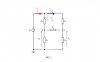
The arrows in that diagram are just to indicate the voltage reference points, ie: the bottom line of your circuit is the ref and the two voltages are measured from that ref point.
No I'm afraid I still haven't solved it yet! ZE has an open circuit equivalence but should I use node or mesh analysis? And what is meant by the 'condition'? Will the final answer just be Vx = Vy expressed in other terms?...I need help please!
This equation is and will be valid for the whole exercise, it is the starting point... What will follow is a consequence of this equation.
So, Vx=Vy means the current in ZE is null. You disconnect it to see more clearly.
Look at the picture I attached.
You are given something, and then tinker with the equations a little bit..
If Vx=Vy , it is then safe to assume that the difference of potential between ZB is equal to that one between ZC.
What does this mean ? Write down the equations in terms of currents. (The currents are I and (I-Ic) )
So, we've got VZA=VZD (1)
VZB=VZC (2)
Write each one in function of the current circulating through each one (example: I-Ic circulates through ZB and ZA so... ? )
You will have two equations on the form X*k=Y*j (1)
W*k=Z*j (2)
The next step to tinker with it would be of course to divide one by the other and get rid of k and j so you only get X/W=Y/Z (And this is equal to (X+Y)/(W+Z) too, we must not forget primary school )
When they ask you about the conditions to get a null current through ZE, something like (Zb+Za)/(Zc+Zd) doesn't mean anything .. It's not an equation or something ..
You got asked what are the conditions to get a null current through ZE, you START from this, from what you have been asked and take it as granted, as your starting point, then you "follow" the consequences of a null current through ZE which are:
*ZA and ZB are juiced by the same current.
*ZC and ZD are juiced by the same current.
VY=VZD=VX=VZA
VIN=VX+VZB=VY+VZC , with VX = VY, so they cancel each other we'll have:
VZB=VZC
What does this mean, we write that in currents going through them:
VZB=ZB*(I-Ic)
VZC=ZC*Ic
VZB=VZC ==> ZB(I-Ic)=ZC*Ic .... (1)
VX=VY , written another way ZA(I-Ic)=ZD*Ic ..... (2)
We divide (1) by (2) to get rid of currents to find the CONDITION to have a NULL current on ZE.
So (1)/(2) gives : ZB/ZA=ZC/ZD=(ZB+ZC)/(ZA+ZD) or written in another way, ZB*ZD=ZC*ZA.
That's the condition one the impedances ZA, ZB, ZC and ZD to get a null current on ZE.
So in your circuit, if you chose for example ZB=10 ohms, ZD=2 ohms, ZC=1 ohms, ZA=20 ohms, you'll get a null current on ZE.
Have a look on Wheatstone bridge, but no matter what, in this kind of problems, you are given a constraint, and you kind of "backward" engineer or reverse stuff to get to *satisfy* this constraint.
(In Control Systems for example, you are given desired characteristics of a system (overshoot, damping, pulsation -for a specific sampling time for example-), and you -backward find- its discrete transfer function, and backward find the propper corrector to do that, R-S-T or a special case Pole Placements, etc.. You do the reverse path, you *start from the end* and find the setting to get the desired output)
This site uses cookies to help personalise content, tailor your experience and to keep you logged in if you register.
By continuing to use this site, you are consenting to our use of cookies.

 )
)