Continue to Site

Welcome to our site!

Electro Tech is an online community (with over 170,000 members) who enjoy talking about and building electronic circuits, projects and gadgets. To participate you need to register. Registration is free. Click here to register now.

  • Welcome to our site! Electro Tech is an online community (with over 170,000 members) who enjoy talking about and building electronic circuits, projects and gadgets. To participate you need to register. Registration is free. Click here to register now.

Resistors etc

Status
Not open for further replies.

oxfordjon

New Member
Evening all, (depending where you are of course)

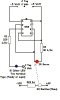
Can anyone tell me what they think the 'R' values should be in the 2nd attached schematic and in the 1st if poss looking at the bottom of BD679 which pin is which and the Voltage of the 1000u caps for best results, the unit is disigned to give fairly high burst output via a momentary action swich to throw a solinoid

Cheers, promise to stop hasseling you and get building after this.

:D
 

Attachments

  • fig4.jpg
    fig4.jpg
    22 KB · Views: 374
  • cap_dis_circuit.gif
    cap_dis_circuit.gif
    4.3 KB · Views: 370
Your fig4 has some problems: the 555 is triggered when pin 2 is pulled low, but the IR receiver goes to +5. also, the output goes high when pin 2 is pulled low, but goes low when pin 6 is pulled low, so the connection is at cross-purposes.

The connections for the BD679 are: emitter - collector - base, left to right looking at the face of the transistor. the info is on the data sheet but you have to hunt for it. https://www.futurlec.com/Transistors/BD679.shtml
 
I agree that the 555 circuit isn't drawn correctly.

The BD679 circuit also doesn't make sense. If there is a solenoid at its output with a low resistance, then the BD679 won't turn on.

Is the high-current pushbutton switch at the circuit's output and feeds the capacitor's charge into the solenoid? Then when the capacitor's voltage discharges low enough, the BD679 turns off the rectified input current from continuing to activate the solenoid.
Surely a fast-rising and fast-falling pulse from the 555 as a monostable timer driving a high-current Mosfet would work much better.
 
Status
Not open for further replies.

New Articles From Microcontroller Tips

Back
Top