Atmaweapon
New Member
I'm wondering if someone is willing to send me in the right direction regarding my voltage/resistance calculations...
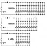
So using that rotary switch you guys suggested yesterday (thanks again for that btw) I've realized I can simplify my circuit down to just three different switch settings - one with 16 LEDs on, one with 12 on, and one with 8 on [Pictured below].
Each LED is rated for 20mA at 3.2V, so when the switch is set to light all 16 LEDs I need to put 320mA across the parallel LED array; likewise when 12 are lit I need 240mA, when 8 lit 160mA. What is the best approach to calculating the size of the parallel resistor for each LED branch, and the size of the main series resistor for each of the three switch settings? I've tried reducing each parallel branch into a single load (3.2V @ 320mA, 3.2V @ 240mA, and 3.2V @ 160mA) I don't think that's right...
Hope this all makes sense. I included the full circuit I redrew at the bottom for context.
Thanks.