Continue to Site

Welcome to our site!

Electro Tech is an online community (with over 170,000 members) who enjoy talking about and building electronic circuits, projects and gadgets. To participate you need to register. Registration is free. Click here to register now.

  • Welcome to our site! Electro Tech is an online community (with over 170,000 members) who enjoy talking about and building electronic circuits, projects and gadgets. To participate you need to register. Registration is free. Click here to register now.

Resistor Resistance

Status
Not open for further replies.

fighterdion

New Member
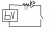
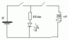
Hi, for a school project i need some resistors, but i dont know the value i need... It must be a resistor to make a 1.2V-1.5V LED work on 6V. With other words, i need a 6V to 1.2V-1.5V resistor. Please give me the value i need.

Greetz
Dion
 
If the diode drops 1.5volts at 20ma's you'll need a 220ohms resistor at 6 volts.
 
Will this work then?

I made a quick circuit... will this work (srry for bad english)
 

Attachments

  • cirquit.jpg
    cirquit.jpg
    8.9 KB · Views: 229
Nope, the LED would always be on and the switch would short out the battery. Attach the resistor inline with the LED and the switch inline with the LED to the battery.
 
I love mspaint <sarcasim>
 

Attachments

  • schematic.PNG
    schematic.PNG
    3.4 KB · Views: 200
...

Look, the LED (in my sheme) is an indicator that the sys is online (after battery there will be a switch so i dont burn all the time). There for i need the resistor. If i press th press switch above my LED, there will go 6 volts to a glowing wire, so it can ignigt a fuse. This is for an huge fireworks show at the 31 December at my school (yeah they got a licence). I was pointed to make an ignition system. please help guys, the ignigters are done, now onley the cirquit!!!

I will make a betteer sheme of the idea now
 

Attachments

  • cirquit.jpg
    cirquit.jpg
    11.9 KB · Views: 201
Last edited:
fighterdion,

If I read your circuit right, the one with two switches, you want a "system on" switch and indicator...also a "detonator switch" with an LED to indicate that the igniter circuit is connected. The attached circuit should do that. R1/D1 indicate power is applied to the system. R2/D2 indicate a complete circuit through the igniter. The pushbutton switch bypasses R2/D2 and provides full current the the igniter when pushed. Are you going to have multiple ignition pushbuttons?

Ken
 

Attachments

  • IgnitorSwt.JPG
    IgnitorSwt.JPG
    13.6 KB · Views: 193
KMoffett said:
fighterdion,

If I read your circuit right, the one with two switches, you want a "system on" switch and indicator...also a "detonator switch" with an LED to indicate that the igniter circuit is connected. The attached circuit should do that. R1/D1 indicate power is applied to the system. R2/D2 indicate a complete circuit through the igniter. The pushbutton switch bypasses R2/D2 and provides full current the the igniter when pushed. Are you going to have multiple ignition pushbuttons?

Ken
Won't that run power through the ignitor as soon as the system on switch is closed? I should think the circuit you would want for adding an LED to indicate ignitor activity would look something more like the attached (forgive my mspainting of your scheme)
 

Attachments

  • IgnitorSwt.JPG
    IgnitorSwt.JPG
    14 KB · Views: 174
KMoffett said:
fighterdion,

If I read your circuit right, the one with two switches, you want a "system on" switch and indicator...also a "detonator switch" with an LED to indicate that the igniter circuit is connected. The attached circuit should do that. R1/D1 indicate power is applied to the system. R2/D2 indicate a complete circuit through the igniter. The pushbutton switch bypasses R2/D2 and provides full current the the igniter when pushed. Are you going to have multiple ignition pushbuttons?

Ken

Yes, i want to make multiple ignigte buttons (about 5 - 10)
 
fighterdion said:
ty! that was what i where looking for! +rep

If you had explained exactly what you wanted to do in the first place, it would have been easier for others to help you. All you said originally was that you wanted to light an LED, and you required the appropriate resistor value. There was no mention of creating an ignition system, and hence Sceadwian was not able to offer you advice in that regard!

Brian
 
Attached is a circuit for 3 buttons/3 igniters. You can see what I duplicated for each additional button/igniter.

Darth,
The resistor (R2) and LED (D2) limit the current through the igniter so enough current passes to light the LED, indicating a complete circuit, but not flash the igniter. Once the pushbutton is pressed, these are shorted out and full current is supplied to the igniter.

I think the 220 ohm resistor (D2) is probably high enough to provide a safe current, but this is a guess. 1000 ohm resistors for D2 would be even safer, but with some reduction in LED brightness.

Also, from the information so far in this thread, I'm not sure attempting to create control circuits for explosive devices is a good idea with the level of understanding of basic electronics shown. I hope there's someone knowledgeable on-site that can check your work. I've been in hobby/medical/scientific electronics for about 50 years, and I would be very reluctant to want stake other's safety on what's been shown. I've built enough circuits over this period to know errors can be made even in the simplest of circuit assemblies...especially if one doesn't know why a circuit is designed the way it is.

Just a strong caveat!

Ken
 

Attachments

  • IgnitorSwt2.JPG
    IgnitorSwt2.JPG
    31 KB · Views: 186
Yes. That's the exact idea of the circuit. Shorting the igniter across the 6v battery causes a large amount of current to flow, causing the igniter to "explode". The exploding igniter is what lights the...what ever your trying to launch. Once the igniter explodes that circuit is no longer complete and no more current flows. Then...on to the next button.

Are you sure you really want to attempt this?


It also appears that your comment about won't pushing the button cause a short, the reason for this response, seems to have disappeared. ????
 
Last edited:
srry, but i was reading your comment again, and deleted my commend on that. I was testing with it only with a battery and the igniter (so no short at all) and than he did it
 
fighterdion.

You can send me a PM.

I can explain it in Dutch for you.

(translation in Dutch)

Jij kan me een privé bericht sturen.

Ik kan het in Nederlands vertalen.

Regards

Raymond
 
Hi Fighterdion, you may find it beneficial to fit a key operated switch on the battery supply (system arming) switch. You can remove the key while the switch is set to off and that way it will stop anyone operating the system who is not allowed to and adds a safety feature too!.

Les
 
Status
Not open for further replies.

New Articles From Microcontroller Tips

Back
Top