Antey
New Member
Hello Everybody ")
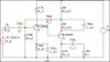
I would like to ask You for expressing your opinions about this so-called design It's simple amplifier, which should have 45 dB gain @ 30 Hz - 100 kHz bandwidth. There's "little" problem with characteristics - phase crosses 0 at highest frequencies (circut is unstable?). I enclose schema & SIMetrix plotted characeristics for reference.
Any comments, sugestions about possible flaws, improvements etc are highly desired and welcomed
[capacitors' values are...well ... experimantal at this stage]
Best Regards,
Peter
I would like to ask You for expressing your opinions about this so-called design
It's simple amplifier, which should have 45 dB gain @ 30 Hz - 100 kHz bandwidth. There's "little" problem with characteristics - phase crosses 0 at highest frequencies (circut is unstable?). I enclose schema & SIMetrix plotted characeristics for reference. Any comments, sugestions about possible flaws, improvements etc are highly desired and welcomed
[capacitors' values are...well ... experimantal at this stage]
Best Regards,
Peter