Continue to Site

Welcome to our site!

Electro Tech is an online community (with over 170,000 members) who enjoy talking about and building electronic circuits, projects and gadgets. To participate you need to register. Registration is free. Click here to register now.

  • Welcome to our site! Electro Tech is an online community (with over 170,000 members) who enjoy talking about and building electronic circuits, projects and gadgets. To participate you need to register. Registration is free. Click here to register now.

Request: 4x4 LED Array selector ideas

Status
Not open for further replies.

GandalfPR

New Member
My wife needed from me an idea for designing a simple Assistive Equipment to be used by disabled children for one of her Speech and Language Therapy courses and I thought on designing a small square box with a 4x4 array of LED's (16 LED's) connected to a push button that while it is being pressed the LED's shall be turning on one at a time in order from left to right and then going to the next row and so on until that sequence will start again.

It seems to be a simple pattern and I wish to get some ideas on how to build this device. I just want to know if there is an IC available that I can use for this purpose or if I will be needing several logical gates (AND's, OR's, etc) for the design.

I'm an electrical engineer, but I'm afraid (and a bit embarrassed) that I forgot most of the theory learned at College at this point (it has been about 13 years since that moment... lol!) and I know that at that moment that would be a simple design that I could make myself in 5 minutes probably but at this point I'm out of ideas.

Please anyone let me know if I can get any ideas on this.

Thanks,
 
Its a possibility but on her project it was specified that it shall be cheap and easily constructed for anyone who wants to make it by themselves. I can program easily a microcontroller, but I know that many people don't have the knowledge to do that.

Thanks for the tip.
 
GandalfPR said:
Its a possibility but on her project it was specified that it shall be cheap and easily constructed for anyone who wants to make it by themselves. I can program easily a microcontroller, but I know that many people don't have the knowledge to do that.

The phrase "cheap and easily constructed" makes a micro-controller even more applicable to the design. As you can program them, you could sell pre-programmed chips for people who don't have the capability.
 
yes, and consider the alternative... probably a complex logic circuit with a whole lot of IC's... that will certainly be much harder for someone to make for themselves!
 
Or, one 7493 counter (or equivalent) and one 74154 decoder (or equivalent) ...
JB
 
yes use a 74154 it as 16 outputs on one chip,but use a 74193 this way you can go back and foward if you want to, and for the 74154 the outputs are high at all time and you will get a black dot moving, to get a moving dot (LED) you need 7404 to invert the output .
i scaned the circuit of that setup but it dosent have the inverter on it
**broken link removed**
 
I found the following schematic that does exactly what I want to do but with 10 LED's and using one CD4017 and one 555 timer as suggested by eblc1388.

How can I change this design to get the 16 LED's loop sequence? How can I implement the IC's jbeng suggested?

Regards,
 

Attachments

  • walking_led_schematic.jpg
    walking_led_schematic.jpg
    33 KB · Views: 1,137
GandalfPR said:
I found the following schematic that does exactly what I want to do but with 10 LED's and using one CD4017 and one 555 timer as suggested by eblc1388.

U1 and U2 are held in reset state so both U1 & U2 Q0 go HIGH. However, no led is lit because the top NPN transistor is OFF. Clocking from 555 has no effect on these two counters.

When user pushes the button, the reset signal on U1 is removed and the top NPN is biased to conduct and the first LED lights up. 555 timer pulses would then advances the counts to 4017 and the corresponding output LEDs.

The trick here is to prevent the second 4017 from counting but enable it after the first 4017 reaches the Q9 state. As the clock is provided to both 4017s, the next 4017 would then count up. When it reaches Q8 state, Q8 output goes high and sends a reset to the first 4017 and the cycle begins again if the Push button is still pressed.

If user releases push button at any time, both U1 and U2 are then reset waiting for next operating.

It is advisable to power the 555 and the rest of the circuit continuously. Do not use TTL as they are expensive, large(24Pin decoder IC), requires +5V regulated power supply and take too much current while idle. For 555 and CMOS circuit, you can use any supply voltage from 4.5V to 12V and the only change needed is the 330R LED resistor. You may conside using the CMOS version of 555 timer to furthur reduce current consumption.
 

Attachments

  • walking_led_16z.jpg
    walking_led_16z.jpg
    60.1 KB · Views: 925
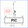
There is another option for you to consider. The circuit that uses a PIC is so much simpler and in many case cheaper than buying all the IC and transistors.

As Nigel has commented, people have to order parts anyway so they might as well get the PIC or a complete kit from you. I reckon a suitable PIC would cost no more than US$2 for this project.
 

Attachments

  • pic-16ledy.gif
    pic-16ledy.gif
    8.2 KB · Views: 825
Guys, it has been a very impressive experience all the suggestions that I got from you. I will implement these ideas and I promise that I will take photos of the final prototype to share with you.

Thanks for all the help!!!!!
 
musthave said:
... and for the 74154 the outputs are high at all time and you will get a black dot moving, to get a moving dot (LED) you need 7404 to invert the output .
That will be your output if you connect the anodes of the LEDs to the chip outputs and the cathodes to ground. If you connect the anodes of the LEDs to Vcc (thru a suitable current limiting resistor) and the cathodes to the chip outputs, you'll get the opposite. You also will only need one current limiter resistor, as only one output is active at a time.
JB
 
did not know about that as i always use triac to drive 120volt lights with it and i always had to uses inverter to get the result needed. so for leds you just have to invert them and uses a resistor, good thing to know Thank you for the info jbeng.
 
I haven't found the 4017 counter but in a store nearby they have available the 4020. Can I use that IC instead of the 4017? Do I need to modify significatively the schematic above?

Thanks!
 
Hi guys,

This really would be a 'cute' project for a little 8-pin PIC ($1.60 USD)... The LEDs are multiplexed using the N(N-1) scheme and could be scanned one column at a time (from schematic point of view) for decent brightness at a 20% duty cycle and a >100-Hz refresh rate using a Timer 2 interrupt routine... Use high efficiency low current LEDs (5-ma) and you could probably run the thing off a couple AA batteries for a good length of time and the hardware couldn't get much simpler; an 8-pin PIC, 6 resistors, a 0.1-uf bypass cap', and up to 20 low current LEDs... Pretty cool -- yes, no, huh?

Regards, Mike
 

Attachments

  • led_chaser.jpg
    led_chaser.jpg
    61.7 KB · Views: 330
GandalfPR said:
I haven't found the 4017 counter but in a store nearby they have available the 4020. Can I use that IC instead of the 4017? Do I need to modify significatively the schematic above?

Thanks!

No, you can't use 4020 to replace 4017.
 
Status
Not open for further replies.

Latest threads

New Articles From Microcontroller Tips

Back
Top