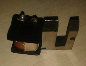
I have a small core with only a primary coil (input). This wire has been broken, so I need to replace it.
The problem is I only have another AWG wire, so I need to use the new thicker wire.
I don't know how many turns I need in the primary. How can I calculate it?
The transformer is a part of an air pump. So it has only the primary and has not secondary coil.
The problem is I only have another AWG wire, so I need to use the new thicker wire.
I don't know how many turns I need in the primary. How can I calculate it?
The transformer is a part of an air pump. So it has only the primary and has not secondary coil.
")
