Continue to Site

Welcome to our site!

Electro Tech is an online community (with over 170,000 members) who enjoy talking about and building electronic circuits, projects and gadgets. To participate you need to register. Registration is free. Click here to register now.

  • Welcome to our site! Electro Tech is an online community (with over 170,000 members) who enjoy talking about and building electronic circuits, projects and gadgets. To participate you need to register. Registration is free. Click here to register now.

repairing a sharp calculator

Status
Not open for further replies.

mdanh2002

Member
Hi,

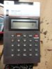
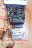
I got an old Sharp EL-1195 calculator from eBay, together with other vintage equipments, for a cheap price. It is a simple calculator with a mini printer (see attached image - pic1.jpg).

This calculator uses a 3.6V DC power adapter and has a rechargeable battery. My purchase does not come with a DC adapter so I use a bench power supply and adjust the voltage to be exactly 3.6V instead. However, the calculator does not turn on at all upon power being applied. The LCD and the printer shows no sense of life whatsoever.

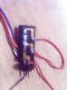
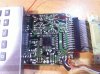
I opened it up and noticed that the rechargeable battery has leaked significantly. I removed the battery, and with the 3.6V DC power being applied, measured approximately 3.3V between the wires connecting the battery terminals. The 3.3V is approximate because it could increase or decrease slightly (3.2V to 3.4V) with small variations in the input power supply. I also identified a 47uF 10V electrolytics capacitor which has gone high in ESR (2 Ohm) and replaced with with a new 47uF 25V capacitor (see attached image - pic2.jpg)

However, with the capacitor replacement, the unit refuses to turn on. What is interesting is that the ON/OFF switch seems to have no effect on the voltage measured. The voltage measured at the battery terminal remains 3.3V regardless of whether the power switch on the calculator is ON or OFF. I also try to short the pins on the switch circuit board but the voltage remains unchanged

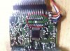
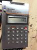
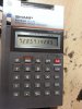
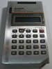
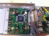
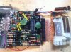
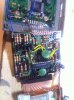
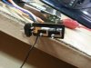
I try to look through the PCBs but nothing obvious. There is some corrosion at the leads of some of the resistors but upon cleaning, there is no difference in the output voltage. There are some points on the PCB traces which are marked as "+" - I measured voltages across those points with respect to the GND pin connected to the rechargeable battery. Apart from one point which measured 3.3V (this is connected to the positive terminal of the rechargeable battery), most other points measured around 0.8V (see attached images - pic3, pic4, pic5). One of the points marked as "+" shows a 0.15V 50Hz signal when measured on my oscilloscope. Interesting.

Unfortunately, my usual debugging techniques for digital circuit (identify the IC, find datasheet and measure the supply voltage or the clock) doesn't work. None of the part numbers (SC1J11 43513 for the LCD processor, SC6735U 1J for the printer processor and M5123L 1401, M5438P 812200 for the power supply board) has any useful search results on Google. I can't find any datasheet. Maybe they are in-house parts?

Any ideas how I can troubleshoot this calculator and get it back working? Can I assume that the power supply is OK since it produces 3.3V and proceed to look for other issues?
 

Attachments

  • pic1.jpg
    pic1.jpg
    14.2 KB · Views: 238
  • pic2.jpg
    pic2.jpg
    1.6 MB · Views: 266
  • pic3.jpg
    pic3.jpg
    1.8 MB · Views: 276
  • pic4.jpg
    pic4.jpg
    1.9 MB · Views: 285
  • pic5.jpg
    pic5.jpg
    1.9 MB · Views: 274
Last edited:
Besides measurements, your diagnosis is built based on what you can see on the LCD, which is nothing.

A dead end, I presume.

At the bottom edge, near the 3,3V area, there traces of what could be leakage from the battery?
 
My expectation of the behaviour if this unit is working, or even partially, once power is applied is as follows:

1. The LCD would turn on (or at least show some of its segments)
2. The printer head would show some movements (to calibrate upon power-up)
3. The trace marked as "+" on the board, presumed to be the voltage rail, would show higher voltage. 0.8V seems too low to me.
4. The switch would cut off power to the board totally once it is off. I still measured 3.3V even with the switch board removed from its housing.

Below is my suspicion:

1. The power supply board is partially dead. But if so, why do I see 3.3V at its output? Why wouldn't the switch have any effects? Maybe the switch circuit has some issues, but I couldn't tell exactly where.
2. The ceramic capacitors are dead (unlikely). I have already replaced the high ESR electrolytics capacitor. Should I replace the ceramic caps?
3. Some resistors have gone high in value. I measured all of them in circuit and they seem to show reasonable value - although without removing them from the circuit (which would be a last resort), it would not be possible to compare the measured value with the color code and see which one is out.

I will try once more to clean the leakage from the board and see if that makes any difference.

Any other ideas?
 
Did you check the power switch is working?
 
You'd be kicking yourself it it had turned out to be the fault, after you spent days on it though, eh? (done that...)
 
Pretty tough to debug circuits via photos. But I can give some thoughts. You may never find the component data sheets. There are a couple of Mitsubishi parts, but most likely custom.

The "+" signs you see could easily be for photo allignment of pick and place machines and may not refer to any particular traces or points. This is also likely since usually specific test probe points are labeled if you are expected to measure there.

There are 4 wires running from your power input switch board. You need to identify what the function of each one is. The Ground and Switched power are two obvious ones. One of the others could be Unswitched Power. But what is the 4th wire for? Could your battery pack have had a middle voltage that needs to be supplied? Your photo doesn't show enough of this to make it clear; like where the battery pack connected and where the wall adapter connected.

I always look for the power traces on the PCB. Either thicker or obviously going to the filter caps and likely power supply pins on the IC's. THey often are the ones that your photo shows going around the perimeter of the PCB. You should be able to trace these back (or use an ohm meter) to the 4 wires from the switch board.

I am also unhappy that you had to replace the electrolytic cap. I do this all the time on old tube radios and TV's. But not on this level of modern device. So I am suspicious that there was a reason for it to fail, like an AC adapter being plugged in, instead of a DC. Maybe a adapter with too high a DC voltage. But whatever it was that casued the cap to fail, most likely caused other components to fail.

Good Luck. The Repair Cafe events that I fix things at do not have high repair rates for fixing items like this. Because even if you do identify a specific failed component, it is unlikely that you can source the part to replace it. Only if it is in the battery pack, immediate power supply do you have a chance.

-Jim
 
Hi JimW,

Thanks for the detailed suggestion. I followed your suggestion and made some further observations today:

1. The power switch board has 4 wires: blue (GND), white (VCC), orange and brown. Orange is connected to the IC SC6735U on the board just before the printer mechanism, presumably for power. Brown is connected to a pin on the printer mechanism connector cable.

2. From its position and arrangement on the board, the switch most likely shorts the orange and brown pins when in the ON position. However, the switch is entirely plastic and I am not sure how it could possibly work. Perhaps there is some metal part beneath the switch which had already been lost when I received the calculator, or was lost during disassembly (see pic3.jpg, switch housing in red, circuit board in blue and plastic switch in yellow)

Whatever it is, I manually soldered the brown and orange pins together (pic4,jpg) and it still does not work.

3. The voltages on the brown and orange wires are not consistent. They are in the range of 0.3 to 0.7V but may sometimes jump to 0.9V or 1V. This is regardless of whether the switch is in the closed position or not. Touching the metal part of the printer mechanism while measuring will cause an increase in the measured voltage, presumably because the printer mechanism casing is connecting to GND. Perhaps a floating ground somewhere?

4. There is a broken PCB trace connecting the orange wire to SC6735U IC. Fixing this by soldering a bypass wire does not help (pic1.jpg)

5. Most importantly, I identified 2 points, at the leads of 2 different resistors, that are shorted together (pic2.jpg, highlighted in red). They are near the group of 3 resistors where I have earlier identified some battery leakage and cleaned it.

The top point does not seem to have any PCB trace connected to it. The short starts with the bottom point, and continues along the PCB trace until it ends at the resistor in the middle (highlighted in yellow, next to the custom Mitsubishi parts).

I also measured the 3 resistors in-circuit:

1. Left resistor: around 65 kOhm with leads in either direction
2. Middle resistor: 500 kOhm in one direction and open in the other direction, with value increasing slowly until it finally reaches infinite.
3. Right resistor: 2.6 kOhm in either direction.

So I think the focus is now on these resistors and why there are shorts. But I guess perhaps the PCB is multi-layered so it is difficult to check by following the PCB trace alone.

I also suspect my assumption on how the switch works. Why does it short the brown and orange wires - kind of strange.

Any other suggestions? Thanks a lot :)
 

Attachments

  • pic1.jpg
    pic1.jpg
    1.8 MB · Views: 209
  • pic2.jpg
    pic2.jpg
    745 KB · Views: 198
  • pic3.jpg
    pic3.jpg
    686.7 KB · Views: 189
  • pic4.jpg
    pic4.jpg
    830.3 KB · Views: 186
Last edited:
A few observations. Middle resistor in your description is open circuit and should be replaced. The slowly rising reading you get is from a capacitor somewhere being charged by your meter.
The switch should have a metal part inside the plastic slider. It would probably have looked like a little clip, or like a leaf spring.
It's a bit hard to tell from the photos, but the board material looks suspiciously like SRBP, which definitely wouldn't be multi-layer, and since this looks like it was made in the 80's, multilayer boards were uncommon then anyway.
I would hazard a guess that the switch extra contacts are to do with charging or running on the battery. Possibly it has 3 positions.
With regards to your jumping voltage readings, I would look for a bad joint on one of the boards, a failing semiconductor or some kind of chemical activity. I would re-flow all the joints with a soldering iron, and test all discreet semiconductors. Probably quicker than trying to locate the source of the readings the proper way.
 
Hi throbscottle,

Thanks for the suggestions!

It's a bit hard to tell from the photos, but the board material looks suspiciously like SRBP, which definitely wouldn't be multi-layer, and since this looks like it was made in the 80's, multilayer boards were uncommon then anyway.

The reason why I though this PCB is multi-layer is because the top of the resistor where I identified the short does not seem to have any visible traces connecting to it, and yet it somehow is shorted to another point. This can't be the case for a single layer PCB. Strange.
The switch should have a metal part inside the plastic slider. It would probably have looked like a little clip, or like a leaf spring.

I guess the metal part of the switch was loose and was lost when I dropped the switch a few days ago. I check the switch casing and there are only 2 positions - probably the switch PCB design is shared with other models that have 3-position switches.

A few observations. Middle resistor in your description is open circuit and should be replaced. The slowly rising reading you get is from a capacitor somewhere being charged by your meter.

After replacing the middle resistor (470 Ohm according to the colour code), I tested the switch board circuit again. This time I measured the current consumption of the calculator as I shorted different combinations of the wires on the board.

It turned out that my assumption that the switch shorts the brown and orange wire is wrong. When these 2 wires are shorted, the circuit consumes 4 uA, too low for such a calculator. When blue (VCC) and brown are shorted, the circuit consumes 8.8mA. When blue and orange are shorted, the circuit consumes 1.9mA.

I decided to test with the VCC and brown wire shorted (see img1.jpg), and suddenly, BIG SUCCESS! The current consumption reduced to 0.13 mA and the calculator LCD turned on, showing a perfect 0 (see the photos).

The calculator now works well - although most function key press (except for digit key 0-9, decimal point, +/-, = and MODE keys) would turn off the LCD for around 10 seconds, raising the current consumption to 8.8 mA again, and when the LCD is finally back on, current reduces to 0.13 mA. The calculations are actually performed correctly, however. So I guess the ICs are fine.

It should be noted that when the LCD is off after a key press, voltage on the orange wire is 1.8V. When the LCD displays normally, this voltage measures 0.6V. The calculator registers the key presses when the LCD is off and shows them later when it's on again.

With some big progress, the question now is to find out why the LCD would turn off for 10 seconds and the current consumption increase upon the operation key presses (+ - * /). The calculator manages to turn on instantly once power is applied, and when the ON key is pressed after being turned off via the OFF key.

My guess could be it's trying to print but the printer mechanism fails, causing the high current consumption. So it will be good to figure out how to get the printer working, or to turn off printing (if the assumption is correct)

Below are some photos of the partially-working calculator.

Look forward to further suggestions. My aim is to get this vintage calculator back in working order!
 

Attachments

  • img1.jpg
    img1.jpg
    566.4 KB · Views: 203
  • img2.jpg
    img2.jpg
    567 KB · Views: 225
  • img3.jpg
    img3.jpg
    638.9 KB · Views: 224
  • img4.jpg
    img4.jpg
    661.1 KB · Views: 208
Last edited:
I managed to disable the automatic printing and make the calculator work like a normal calculator by pressing the MODE key, followed by 7, to switch between printing (P) and non-printing (NP) mode. When in NP mode the calculator will not attempt to print and there will be no delay upon every key press. The problem only happens in printing (P) mode, so the printer was indeed the cause.

As for the PCB, I think it was indeed a single layer PCB. My suspicion of the point at the resistor's end which does not seem to be connected to anywhere is flawed - there is another trace starting from that point on the other side of the PCB which I missed.

My task now is to connect an oscilloscope to the printer ribbon cable and see what signals, if any, are sent to the printer mechanism when it's trying to print and debug from there. Still quite tough, though.
 
Last edited:
Status
Not open for further replies.

Latest threads

Back
Top