RODALCO
Well-Known Member
A while ago our 9 year Westinghouse oven clock packed the sad.
After many requests from the misses I decided to have a look at it.
Sliding the oven out was easier then I expected and the top cover came off with 4 screws.
The clock was of course fixed to the front plate and probably a major task to remove.
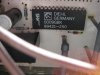
Ok, Yesterday I tackled the problem by measuring the two resistors which were put on stand offs, obviously to dissipate excess heat.
One of the two R's was open circuit. The other R was ok and measured 4700Ω
I did a temp rewire and put a 5100Ω in the place of the open circuit 4700Ω resistor.
The clock worked, hoorah !
The faulty R looked like a 3 Watt resistor.
By measurement I revealed that 105 Volts was dissipated across each Resistor
from: U = I*R the current is 22mA.
from P= I²*R Power is 2.3 Watts
Double that by two makes 4.6 Watts, not very efficient.
In one year makes 40 kWh wasted in those two resistors.
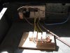
I purchased 4 x 5 Watt ceramic resistors and fitted those on a tagboard away from the clock circuit board, and connected them via jumper leads.
I used a combination of 2200 and 3300 ohms in series twice.
Mainly to reduce power wastage and the clock still works fine.
New current is now 19 mA and and power is 2 Watts, still 4 Watts in total and 35 kWh per year.
Now I see why you hear the old story about the microwave clock that the clock often uses more power over the year than the actual magnetron does in short bursts of time.
Surprising that a small transformer is not fitted instead.
Photo's will be attached in about 30 minutes.
After many requests from the misses I decided to have a look at it.
Sliding the oven out was easier then I expected and the top cover came off with 4 screws.
The clock was of course fixed to the front plate and probably a major task to remove.
Ok, Yesterday I tackled the problem by measuring the two resistors which were put on stand offs, obviously to dissipate excess heat.
One of the two R's was open circuit. The other R was ok and measured 4700Ω
I did a temp rewire and put a 5100Ω in the place of the open circuit 4700Ω resistor.
The clock worked, hoorah !
The faulty R looked like a 3 Watt resistor.
By measurement I revealed that 105 Volts was dissipated across each Resistor
from: U = I*R the current is 22mA.
from P= I²*R Power is 2.3 Watts
Double that by two makes 4.6 Watts, not very efficient.
In one year makes 40 kWh wasted in those two resistors.
I purchased 4 x 5 Watt ceramic resistors and fitted those on a tagboard away from the clock circuit board, and connected them via jumper leads.
I used a combination of 2200 and 3300 ohms in series twice.
Mainly to reduce power wastage and the clock still works fine.
New current is now 19 mA and and power is 2 Watts, still 4 Watts in total and 35 kWh per year.
Now I see why you hear the old story about the microwave clock that the clock often uses more power over the year than the actual magnetron does in short bursts of time.
Surprising that a small transformer is not fitted instead.
Photo's will be attached in about 30 minutes.