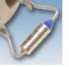
The Morphy Richards - dual control - electric blanket has ceased working. Upon inspection I find that a component I think is a thermal fuse (V100TAM - 103 C 044 - [PS] EJET) does not pass current. I have contacted various suppliers but no one can give me an exact replacement.
Does anyone know how to source the component?
What do you think the current rating is?
If I used a 10A TCO would it do the job or do I risk electrocuting myself?
Help!
Julian
Does anyone know how to source the component?
What do you think the current rating is?
If I used a 10A TCO would it do the job or do I risk electrocuting myself?
Help!
Julian