Continue to Site

Welcome to our site!

Electro Tech is an online community (with over 170,000 members) who enjoy talking about and building electronic circuits, projects and gadgets. To participate you need to register. Registration is free. Click here to register now.

  • Welcome to our site! Electro Tech is an online community (with over 170,000 members) who enjoy talking about and building electronic circuits, projects and gadgets. To participate you need to register. Registration is free. Click here to register now.

Repair a DJ mixer

Status
Not open for further replies.

Rorut

Member
I got a Vestax 05 pro that does not turn on.
Previous owner told me it stopped working after trying using a different power supply. Maybe wrong polarity.

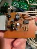
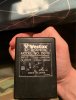
I got the original Power supply.
Spec says DC 15V. Output measures 22V.
I have another one exaclty the same and output on that is 19V.
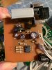
I desoldered:
Q101 and the component tester indicates:
474535EE-B566-4AEE-94AC-3B8122C90D4B.jpeg
Q102 same on that one:
CFC94BF0-C79F-48FD-A988-AC7DE5971C86.jpeg
Diod on the board seems ok.
IC 4558D desoldered and tested with a OPA2134 dual op-amp as a test replacement (only thing I had home).

Nothing above helped.

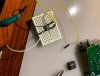
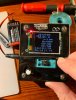
I only get 22V voltage on the red line in the
picture. No other voltage indications.
5E63C50A-2930-4B7A-B3B5-1E8BA5D4CA5C.jpeg


Any ideas what to do next?

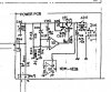
Vestax 05 repair manual:
 

Attachments

  • C39A802E-343A-428D-8BFF-E0593E949B2A.jpeg
    C39A802E-343A-428D-8BFF-E0593E949B2A.jpeg
    127.6 KB · Views: 232
  • 74C974DD-2486-4E14-9249-91A8E7B2D856.jpeg
    74C974DD-2486-4E14-9249-91A8E7B2D856.jpeg
    1.3 MB · Views: 255
  • 61E121DD-8EE5-4761-98DA-015953DB5D47.jpeg
    61E121DD-8EE5-4761-98DA-015953DB5D47.jpeg
    1.1 MB · Views: 191
  • 48CED3B5-12DA-4834-BA4A-B84821E0F093.jpeg
    48CED3B5-12DA-4834-BA4A-B84821E0F093.jpeg
    972.2 KB · Views: 181
Last edited:
PS has a negative tip. In my experience, a pos tip is much more common. Assuming that is what happened (i.e., former user tried it with a pos tip PS), would you suspect that the 8.2V zener (D101) would blow? Can you remove and test? Yes I am just guessing, but enough monkeys at enough typewriters....
 
This monkey suggests that IC101 is toast due to the reversed polarity of the PSU.

JimB
 
PS has a negative tip. In my experience, a pos tip is much more common. Assuming that is what happened (i.e., former user tried it with a pos tip PS), would you suspect that the 8.2V zener (D101) would blow? Can you remove and test? Yes I am just guessing, but enough monkeys at enough typewriters....
I measure 0.7v across diode in one direction and 0v in the other. Removed from board.

This monkey suggests that IC101 is toast due to the reversed polarity of the PSU.

JimB
But why did it not work with the OPA2134?
 
Tested IC101 outside the circuit. 0V on output feeding with the 15V supply.
Also tested the OPA2134 same way and that gave me viltage on output but does it does not solve the problem if I put it in the circuit.
 

Attachments

  • E4D7C483-FD5F-46F8-9061-ADC7BF8E22CF.jpeg
    E4D7C483-FD5F-46F8-9061-ADC7BF8E22CF.jpeg
    1.3 MB · Views: 139
Rorut, what you are doing there is not going to be a reasonable test of an op-amp.

Do something like this:

Opamp Tester.png

If you apply a variable voltage to the input,
With the input at 0v the output will be around 9 volts.
When the input reaches about 4.5 volts, the voltage at the output will start falling.
When the input reaches 9v, the voltage at the output will be around 0v.

Depending on the op-amp type, if it is not "rail to rail" the output may not go below about 2v or above 7v.
But the idea is that you should be able to see a smooth variation in output as the input is changed.

JimB
 
Got it working
Used a LM358 and it started up. I get 12v on ph6,ph7 now.
After that I tried the old ”defective” one again and it started up but gave 16v on ph6,ph7 and chip got burning hot. Pulled it out and wonder if the LM358 would work as a replacement or better order same as the original one (4558)?

Possible to explain why the defective one suddenly started the unit?

And thanks Jim, I learned something.
 
Tested the mixer again today and it will not start normally.
Discovered that it starts if you quickly press the power button several times.

Then once it has started and you turn it off, it starts if you test directly again but if it is switched off for a few minutes you have to repeat this procedure.

The power button measures voltage through regardless so it seems not to be faulty

Tested with another adapter and the same thing there.
 
Last edited:
I replaced the capacitors marked in the picture but that did not help.
 

Attachments

  • 6F694AB8-05AD-4BB9-BFAD-6E464D81D966.jpeg
    6F694AB8-05AD-4BB9-BFAD-6E464D81D966.jpeg
    519.2 KB · Views: 200
The power supply circuits seems to be a bad design.

There is no absolute guarantee the opamp inputs will have any difference before the control transistors turn on, or enough to overcome any offset within the IC - and the IC must give an output for the transistors to start to turn on at all...

Try adding a high value resistor, eg. 100K, between pins 8 and 3 on the IC. That should put a small positive bias on the amp and make the regulator start.

It will fractionally affect the output voltage dependant on the input, but if it works a slightly more sophisticated add-on with an extra diode and a change to one resistor could fix it without side effects.
 
I am wondering about a few things.

When you received this, you said that the original owner replaced the PS and, "we" were assuming that the replacement created the problem (different polarity). So, do you know exactly why the original owner needed to get a replacement? Did they lose the original power supply? Did it go bad? Did the mixer have a few problems and the thinking was that a replacement PS would solve them? I am wondering if the mixer has problems apart from the power supply.

Is it feasible to simply not use that power supply board. IOW for testing just use a known good PS - you said 12V at

Got it working
Used a LM358 and it started up. I get 12v on ph6,ph7 now.

So, use a good 12V power supply connecting to PH6 and PH7 and see if the mixer is working reliably and with no intermittent issues. It might help narrow down what you are dealing with.
 
Try adding a high value resistor, eg. 100K, between pins 8 and 3 on the IC. That should put a small positive bias on the amp and make the regulator start.
Thanks a lot I will try this!

I am wondering about a few things.

When you received this, you said that the original owner replaced the PS and, "we" were assuming that the replacement created the problem (different polarity). So, do you know exactly why the original owner needed to get a replacement? Did they lose the original power supply? Did it go bad? Did the mixer have a few problems and the thinking was that a replacement PS would solve them? I am wondering if the mixer has problems apart from the power supply.

Is it feasible to simply not use that power supply board. IOW for testing just use a known good PS - you said 12V at

So, use a good 12V power supply connecting to PH6 and PH7 and see if the mixer is working reliably and with no intermittent issues. It might help narrow down what you are dealing with.
No other issues with the mixer. Previous owner forgot the power supply at home and tried a different one...
The mixer starts whithout any problems if I feed ph6 and ph7 with 12v computer PSU. Sounds great from both channels
 
Having the original psu connected for a while (until its hot) and then start the mixer there is only a couple of seconds delay and it starts by itself.
Maybe old/bad capacitors in both my oem power supplys i tested with?
 
Last edited:
Status
Not open for further replies.

Latest threads

New Articles From Microcontroller Tips

Back
Top