Continue to Site

Welcome to our site!

Electro Tech is an online community (with over 170,000 members) who enjoy talking about and building electronic circuits, projects and gadgets. To participate you need to register. Registration is free. Click here to register now.

  • Welcome to our site! Electro Tech is an online community (with over 170,000 members) who enjoy talking about and building electronic circuits, projects and gadgets. To participate you need to register. Registration is free. Click here to register now.

Removing DC from into Transformer Primary

Status
Not open for further replies.

AltAudio

New Member
Hello,

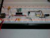
I have an audio signal that's been filtered/amplified and I am trying to preserve the signal as it comes off 2N transistor collector into left primary of transformer. The right primary takes 5V dc and but when happens is that the DC creeps up into left primary and up to collector output. I've tried numerous caps, ranging from 80pF to 470µF and the best I could achieve is minimal preservation of AC signal off collector but no effect whatsoever on left primary of transformer.

Any suggestions?
 
Why would you use DC with a transformer anyway?
 
Post a circuit. I cant figure out what you are trying to do from your description
 
Ok, I will post pic later this afternoon. I'm trying to mimic the function of a device that output electical impulse via transformer. One side is DC 5V and the other is AC inverted 5.8V square wave pulse. The end result is a pretty good zap of electricity. I understand that the counter electromotive force, ie collapsing field is what triggers voltage output, but I thought perhaps I need the DC component as the entire signal is outputted to electrodes to skin.
 
That one zaps pretty well if you turn the pot all the way up.

The 1K resistor limits current through the skin (not to electrocute someone).

I suggest a clock frequency for gate control of at least 16KHz.

Boncuk
 

Attachments

  • DC-AC-SCH.gif
    DC-AC-SCH.gif
    13.1 KB · Views: 133
Last edited:
Removing DC from Transformer Primary

Well here's the circuit. I also included a pic(I know it's not exactly helpful) of device that outputs elec impulse. Underneath the board feeds a DC 5V to left primary of transformer, while the right primary is fed AC pulse (apx 6V) via transistor - as seen in pic. So there seems to be both types of current feeding transformer, and I'm trying to replicate this functionality.
 

Attachments

  • Circuit1.jpg
    Circuit1.jpg
    1.1 MB · Views: 116
  • TENS.jpg
    TENS.jpg
    1.1 MB · Views: 115
Same comment about posting the schematic. Why start another thread, when we still discussing your original circuit?
 
Status
Not open for further replies.

Latest threads

New Articles From Microcontroller Tips

Back
Top