Continue to Site

Welcome to our site!

Electro Tech is an online community (with over 170,000 members) who enjoy talking about and building electronic circuits, projects and gadgets. To participate you need to register. Registration is free. Click here to register now.

  • Welcome to our site! Electro Tech is an online community (with over 170,000 members) who enjoy talking about and building electronic circuits, projects and gadgets. To participate you need to register. Registration is free. Click here to register now.

Remote Computer Switch

Status
Not open for further replies.

jack0987

Member
Hi:
I have two computer servers in my basement so I do not have to listen to their fans run all the time.

I would like to run two pairs of wires from the motherboard of each computer.
- One pair is for a momentary switch to turn them on and off.
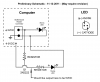
- One pair is for the green LED so I can see if it's on.

I have questions about the LED circuit. Parallel LED's may not be good idea.
I thought when the green LED comes on I could connect a transistor to it to boost the voltage to 5VDC and connect my second green LED with a series resistor at the other end.

Please show me the way as circuits are not my strong point.

Thanks.
 
Each computer has a motherboard header that should resemble what is found on this page. The common for the ATX-SW and the PWR_LED are the same common. If you want to know if each unit is in fact ON then you need to monitor both units status lights. Rather than worry about those ports just tap the computer's 5 volt PSU rails. If the computer is on the PSU 5 volts is on. Both systems should share or can share the same common so that is 3 wires. Add the start momentary and that is 5 lines. You only need a single common for both systems.

Ron
 
Thanks, reloadron.
I can see that 3 wires per computer would be fine. Tapping the 5 volt rail for the status LED would work perfectly until I wanted to expand my little project to the Hard Drive LED and any other status LEDs.

Having, say a 5 volt output, could be also used for external monitoring.

A nice way of doing this may be with the LAN cable except prehaps when the router/switch is not working, access over the phone or web, etc. This beyond my scope. I can build things if told how, that is about it. If you folks have an interest, have at it. should start a new thread, however.
 
Last edited:
Star Tech Computer Parts makes this cute little kit for replacing front panel wiring. For about $6 USD it is worth it just for the connectors. A little splicing a dicing is all that is needed.

My one workstation/server is loud but really doesn't bother me, hell getting old here and don't hear what I once did. Everything here, servers and clients run 24/7 so I never give things much thought. If a server is down I will know it right away. Another consideration would be better fan speed control on the server side of things.

As to a WOL (Wake On Lan) you could toss around a script similar to this:

Code:
Dim objWOL

Set objWOL = CreateObject( "UltraWOL.ctlUltraWOL" )

objWOL.BroadcastAddr = "192.168.0.255"
' The MAC address of the computer to be woken
objWOL.MACAddr = "AA-BB-CC-DD-EE-FF"
' The local computer's IP address
objWOL.LocalIP = "192.168.0.4"
objWOL.WakeUp

The above code in .VBS (Visual Basic Script).

What you need to do is figure out exactly what you want.

Ron
 
Thanks, again.

I will get several of those star tech kits just for the connectors and wires. Well worth the price.

I think just connecting a transistor to boost the Motherboard LED output will do fine for now. Could this be done and what might the circuit look like?
 
I am not sure what the voltage out from motherboard to LED is but you would use a circuit similar to the attached. The 2N2222 (or any common switching NPN transistor) would have a base resistor based on the LED load. The same is true for the resistor in series with the transistor collector LED and and 5 volt supply. You could start with maybe a 1K base resistor and maybe 220 ohms in series with the LED.

If you want to try the code sample let me know and I'll tell you how to set it up.

Ron
 

Attachments

  • LED Transistor.gif
    LED Transistor.gif
    3.8 KB · Views: 141
Thanks.

Going by your sample, I have reconfigured the circuit to look like the attached drawing.

**broken link removed**

Please review and comment.
 
hi
The drawing is enormous , I can see my house!...

Shrunk it down for you.
 

Attachments

  • computerstatusled.png
    computerstatusled.png
    18.3 KB · Views: 157
Last edited:
The earlier drawing I posted had an error with the identification of the LED terminals.

Here is a revised drawing.
Near as I can tell (need a new volt meter) my motherboard has a 3VDC output for it's status LED.
Please review and comment.

**broken link removed**
 
Last edited:
You need to get it like mine. The LED and LED resistor are on the transistor collector. You have them on the emitter.

Ron
 
If I do that, It seems the point before the LED resistor will always be high.
I was trying to use the transistor as a switch.
 
If you set it up as I drew it the transistor serves as a switch. The transistor completes a path to ground when it is on. Yes, the LED and Resistor will always be high if we want to look at it that way. The idea is using an NPN switching transistor (2N2222 or 2N3904 or any basic NPN switching transistor) is when we turn on the transistor we complete the path to ground for the LED and its series resistor.

Ron
 
I can see that the circuit you drew will work, but prehaps will not work in the way I desire.
I think of a switch as being either on or off. This is what I would like. Either a 5VDC output or 0VDC.
My lack of knowledge may cause me to ask the question in the wrong way.
An isolated output, in addition, may help protect the motherboard.
Please comment. thanks.
 
OK, in what I drew if we removed the LED and let's say made the series LED resistor 10K Ohms. If we looked at the collector of the transistor when the base had a signal from motherboard the collector would be about 0 volts (the transistor is switched on). If the motherboard signal is low the same junction would be a 5 volt logic level. So as drawn you could have 5 volts or 0 volts.

I am traveling this week and do not have my drawing software or any of my reference material. So I am somewhat limited but anyway...

Yeah sure, if you want isolation that can easily be done using an opto isolator transistor rather than the basic switching transistor I used. This link provides an overview.

I gave you a circuit design that would mimic the PC front panel LED, what exactly did you have in mind or want?

Ron
 
Figure 1 - For clarity, I have redrawn your original circuit proposal. It should now be mostly correct.

Figure 2 - If I understand you correctly, Figure 2 should represent what you tried to tell me verbally. TEST POINT A will be 0 volts when the computer status LED is on and 5 volts when it off. However, as I see it, the external LED will be off when the computer LED is on. Could we reverse this?
As an afterthought, I think TEST POINT A Should be between the computer 5 volt supply and resistor R3. Please comment.

I will work on the opto isolator next after study.


**broken link removed**


**broken link removed**
 
Last edited:
Status
Not open for further replies.

Latest threads

New Articles From Microcontroller Tips

Back
Top