Continue to Site

Welcome to our site!

Electro Tech is an online community (with over 170,000 members) who enjoy talking about and building electronic circuits, projects and gadgets. To participate you need to register. Registration is free. Click here to register now.

  • Welcome to our site! Electro Tech is an online community (with over 170,000 members) who enjoy talking about and building electronic circuits, projects and gadgets. To participate you need to register. Registration is free. Click here to register now.

Relays (Automobile Related Help Needed)

Status
Not open for further replies.

Shiin

New Member
Before I fry something in my car, I need some clarifications...

Intention:
I am hooking up some fog lights, 2 additional horns, and coolant fan to switches, seperating the switches from the actual powered accessories by means of relays. But i have an issue with lighted switches: read below


Question:
I previously had it hooked up as follows:
(LIGHTED SWITCH)
Battery to Power Prong of Switch
Accessery Positive to Accessory Prong of Switch
Ground Prong of Switch to suitable Chassis Ground
the light on the switches works


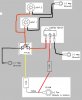
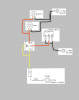
VIEW ATTACHMENT FOR RELAY DIAGRAM
A = From Battery Positive
B = To Accessory(+)
C = To Switching Means (to turn relay on)
D = Chassis Ground (for relay)

Now I hooked it up as follows:
1) Battery(+) to A
2) Battery(+) to C
3) Accessory(+) to B
4) Accessory(-) to Chassis Ground
5) Switch(+) to D
6) Switch(-) and Switch Accessory(+) to Chassis Ground

5 and 6 basicaly run off of prong D of the relay (which is the ground for the relay) and complete the ground circuit of the relay to turn on the relay.

The Accessory turned on in this manner works perfectly like it should, but the switch LIGHT does NOT come on.

The Light of the switch operates only when power comes through the switch(+) and out the switch(-), regardless if switch accessory(+) is attached to an accessory or not.

Right?

Well, in theory, the LIGHT of the switch should come on, regardless if the switch accessory(+) prong is the grounded with the switch(-) prong, because the switch is getting its power from the relay ... is that theory correct?


Im boggling my mind over this electric crap lmao. plz help clarify this issue.


Daniel
 

Attachments

  • relaybasic.png
    relaybasic.png
    5.5 KB · Views: 137
Normally lighted switches in automotive applications come in two varieties. First is the "lights when switch turned on" and second is "lights when power is applied, as in dash lights are on."

Most common is the "lights when switch is on." These usually have three terminals. One is for ground ( the internal lamp only ), another for Battery positive, and third for the load. This way, when the switch turns on, the load gets power, and so does the internal lamp.

See these links, they may help:

http://www.bcae1.com/relays.htm ( wiring a Bosch type relay )
**broken link removed** ( lighted switch and relay )
 
view attachment for new diagram

This is how I have it now. it all works except for the light in the switch. no fuses blow or anything liek that, so it should be a legit connection type eh?

my goal is to only have 3 wires running back into my center console, not 6. I have other things also using relays in this manner, but i need to get one function 1st before i do the rest.
 

Attachments

  • relay2.png
    relay2.png
    12.4 KB · Views: 154
Last edited:
note: lighted switch has contact from PWR to ACC and indicator light from PWR to GR.
the way you connected it, relay is never really off, some leakage current will always flow through it so your circuit might work better or worse depending on charge status of your car battery.
if you remove switch jumper ACC-GR, move wire from relay terminal 85 to 30 and install one new wire from 85 to ACC of the switch, your circuit will be the same as posted reference link. this is just one more wire to the switch.
assuming switch is only device on the console that would be 3 wires going to console.
 
yeah, if I was to use one switch in the dashboard, i'd have no pob doing it proberly; since i'm going to have 6 or more switches on the console tho, i am trying to figure out the least wires to the dashboard while having the ability to use a lighted switch.

I have thought of an idea tho;
Instead of using a lighted switch, I could use automobile type indicator lamps in between the ground of the switch and the chassis ground and only use a normal 2 prong switch (non lighted) - that way there is only one wire to worry about and still get a clean break in the circuit when the switch is off.

I was just curious tho whyt he light wouldn't come on when it was wired as shown in my recent image attachment. mind boggling for sure. ;P
 
The light does not turn on because it is not powered. You have the ground connection to the switch, but the Battery connection of the switch is also connected to ground. The "output" of the switch is now ground when "on". You are doing what is called "lowside" switching, connecting the ground to a device to turn it on. This is normal in cars, but won't work with this type of lighted switch.

If you follow the "lighted switch and relay " diagram above, the switch will light.

For the light to work, it must be connected to both ground and 12 volts ( battery positive ). Your second diagram connects ground to both sides of the internal light, so does your last idea above.
 
Automotive relays for this kind of application normally have the following pins:

85: Run an Earth to here
86: Trigger pin (i.e. feed from main beam switch or horn button etc)
87: Output pin (connect the +ve of each of your spotlights or horns etc to
here)
30: Run your positive 12V supply to here.

Hope this helps!

Brian
 
Last edited:
Another tip: Some relays of these types have two pins labelled 87. With these relays, run one of your spotlights to each of the pin 87's.

Brian
 
zevon8 said:
The light does not turn on because it is not powered. You have the ground connection to the switch, but the Battery connection of the switch is also connected to ground. The "output" of the switch is now ground when "on". You are doing what is called "lowside" switching, connecting the ground to a device to turn it on. This is normal in cars, but won't work with this type of lighted switch.

If you follow the "lighted switch and relay " diagram above, the switch will light.

For the light to work, it must be connected to both ground and 12 volts ( battery positive ). Your second diagram connects ground to both sides of the internal light, so does your last idea above.

Ahhh i think i see where everyone is coming from... The current that is coming out of RELAY GROUND isn't strong enough to light a small lamp or indicator lamp, since relays only allow enough current to pass through them to energize the coil and complete the connection... correct?

I was under the impression that regardless of how I had it hooked up, there was still current running through the ground wire of the relay (to power something else) - in this instance, a lighted toggle switch.


ANywho, I think i will just settle for non lighted toggle switches. or perhaps run the power from a totaly seperate wire from within the dash board to power the lamp in the switch, and still keep the # of wires running from dash to underhood of car, at a minimum.


Meh. Thanx for the help all.
Feel free to post anymore helpfull tips if you think of some. I'll appreciate it greatly! :)


Shiin
 
here try this im quite sure it will work the way you want it.
you will have to put a diode 1n4001 on terminal 85 to 86 to kill spikes from the coil releases.
 

Attachments

  • relayals.jpg
    relayals.jpg
    107.6 KB · Views: 156
Last edited:
i don't see how will this work, maybe you tought of something else...
if wired per last circuit, relay coil will be always connected to gnd
(one or both sides depending on switch position).

before we try to rearrange circuit can someone check if the light indicator
in the switch is polarized (as indicated with + and -) or not...?
 
Last edited:
on the switch (GR - is for the internal light only of the switch)
(pwr+ is for the light and the supply for acc when switched on)
(acc is the 12+ to supply the load or relay when switched on from pwr)
that how a switch I have here is setup, if you where to connect the acc on the pwr then yes you would have neg when off and positive when on.
 
Status
Not open for further replies.

New Articles From Microcontroller Tips

Back
Top