Continue to Site

Welcome to our site!

Electro Tech is an online community (with over 170,000 members) who enjoy talking about and building electronic circuits, projects and gadgets. To participate you need to register. Registration is free. Click here to register now.

  • Welcome to our site! Electro Tech is an online community (with over 170,000 members) who enjoy talking about and building electronic circuits, projects and gadgets. To participate you need to register. Registration is free. Click here to register now.

Relay Via Zener

Status
Not open for further replies.

AtomSoft

Well-Known Member
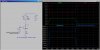
Ok would it be sane and safe to control a 5v Relay using a 5.1v zener with a 12v supply ?.. For instance...

I have some of these:
https://www.electro-tech-online.com/custompdfs/2013/06/en-g5le.pdf

5 VDC 79.4mA relays

so should i do a 100mv / 80mA to find the resistance and use a resistor? (1.25 ohm) to limit the current to 80mA ? Or will the internal resistance handle that?

Kinda lost but seems like a nice cheap way to control a Relay using 7-24v .... :)


FOR EXAMPLE I DREW THIS UP: (EDIT FIXED RESISTOR FOR ZENER)
ZD1.jpg
 
Last edited:
I have often used a simpler method.

The transistor base connects directly to the logic level pin, and when relay is ON the base is at about 4.5v.

Then I use a resistor from the emitter to ground. That acts as a constant current relay driver;
base = 4.5v
emitter = 4.5v - 0.6v = 3.9v
emitter resistor = 3.9v / 80mA = 49 ohms

After that the relay coil (with its diode) are connected between the PSU positive and the transistor collector.

It won't matter if the PSU is at 10v or 24v, the relay coil (when on) will always get 80mA.

Just remember the transistor will dissipate the dropped voltage and may need some heatsinking, although that is still a better option than dissipating the drop on a little zener.
 
Ok to clarify that in my mind you mean like this:
TR1.jpg

Also does this mean i have to use 5v as a source for the transistor ? What if im using a 3.3v system or the actual trigger voltage is 12v?

EDIT:

Thanks for helping me out on this Roman! BTW love that RF Serial stuff on your site :)
 
Here is a schematic taylored for your situation. The port pin swing is 3.3V. The auxilary power supply is 12V. The relay coil resistance is 5V/80mA = 62Ω.

R1 sets the current per the formula shown. The voltage across the relay is 5V. The power dissipation in R1 is shown in lt. blue (use either a 1/2W or 1W resistor), and the power in Q1 is shown in dk. blue (use a heatsink on Q1).

The minimum voltage at V1 is 8V. The dissipation in Q1 when V1 is 24V is a whopping 1.5W. Bigger heatsink.
 

Attachments

  • DF71.jpg
    DF71.jpg
    149.8 KB · Views: 167
Last edited:
Having Resistors in the Emitter of Switching Transistors is bad engineering.

Ramesh

Why? This transistor is not saturated, so it switches much faster than it would if it were saturated. Also, the goal is to drop a voltage and switch a relay that takes tens of ms to do something, not worry about switching speed, anyway.
 
Why? This transistor is not saturated, so it switches much faster than it would if it were saturated. Also, the goal is to drop a voltage and switch a relay that takes tens of ms to do something, not worry about switching speed, anyway.

Yes, you have a point.
But, if you saturate the transistor, The power dissipation will be negligible. So will be the case in cutoff. Why should one operate the transistor in Linear Region if it can be avoided?
In the case under discussion, why not dissipate the power in a series resistor instead of the transistor?

Ramesh
 
All that aside, is it safe to assume voltage is not they key factor when driving most electro mechanical devices? Ive noticed people driving steppers using 24v and its rated for 3v, I've never understood how/why.
 
No, it's not safe.
Stepper coils have inductance, which prevents instantaneous current increase when voltage is applied. For high speed operation a rapid increase is required. Rate of rise of current is greater when the applied voltage is increased, but care must then be taken to limit the final current to a safe value which won't cause over-heating of the coils.
 
Yes, you have a point.
But, if you saturate the transistor, The power dissipation will be negligible. So will be the case in cutoff. Why should one operate the transistor in Linear Region if it can be avoided?
...

I agree saturation is good and means the transistor runs cooler. But the desire in this case is to run the relay coil at a fixed voltage or current (fixed coil power). This circuit does that very well and is used in industry and auto electronics to make sure the relay is driven with correct coil current, even if the PSU voltage varies.

...
In the case under discussion, why not dissipate the power in a series resistor instead of the transistor?

Because then the coil current will vary as the PSU varies, and it costs an extra power resistor. This is actually safer as the coil current is always good (assuming PSU volts>min). It can also be efficient as you can choose a lower coil current which will still activate the relay reliably, and will always be fixed at that current.

Normally relays allow for a wide operating voltage range, so a typical 12v relay coil will work fine from 7v, but at 14.4v in a vehicle it wastes power and the coil runs quite hot.
 
Status
Not open for further replies.

New Articles From Microcontroller Tips

Back
Top