Continue to Site

Welcome to our site!

Electro Tech is an online community (with over 170,000 members) who enjoy talking about and building electronic circuits, projects and gadgets. To participate you need to register. Registration is free. Click here to register now.

  • Welcome to our site! Electro Tech is an online community (with over 170,000 members) who enjoy talking about and building electronic circuits, projects and gadgets. To participate you need to register. Registration is free. Click here to register now.

Relay ULN2803 Circuit

Status
Not open for further replies.

bh00

New Member
Hey,

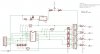
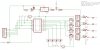
I'm trying to build a small circuit that will let me control some water valves from a microchip. This is the circuit I came up with. Is the basics of the chips setup right? The chip on the left is an optocoupler (TLP621-4) and the chip in the middle is the ULN2803. The relays are only small (the part numbers top right refer to rapid electronics). The relays are 5v with 500ohm resistance. So I guess this would work ok and to turn on a relay I just ground one of the control wires, but can someone just give it a once over before I get a prototype PCB made up...

Thanks :)
 

Attachments

  • relay board schemetic.JPG
    relay board schemetic.JPG
    78.5 KB · Views: 11,248
500 ohm relay coil seems very high but, if that's correct, they will only draw 10mA.

In that case, you don't need to double up the uln2803 drivers. just one should be ok. each one can drive more than 10X that current.

Your opto's look wired wrong. there should be a limiting resistor in series with the LED. the transistor should be wired shown in the attachment a wire from the collector going to the uln2803. ignore the R1 and the +12V connection for the lED, that was drawn for a different application

Also, I don't understand why you have extra LEDs and what they are attached to.

However, you might just get away with using the opto's transistor to directly drive (er, pull) the relay coil since they are pulling 10 mA

If you haven't breadboarded this circuit, I would do that before getting a pcb made.
 

Attachments

  • opto.gif
    opto.gif
    3.3 KB · Views: 3,844
Last edited:
Ah ok, I was only guessing the opto wiring because I haven't used them before.

I would breadboard it first but I can get the proper PCB done with dual layers and soldermask for only like £6 for a one off so its easier just to do that.

The relays I'm using are **broken link removed**, so I guess they only draw 10mA? I'm using them to control 12v soleniod valves which draw 4W so I hope they're suitably rated.

I know I don't need to double up the drivers I just did because I had the spare channels but I spose it'll simplify wiring not to :) The extra LEDs are just meant to be indicators that a relay is on because they'll be pulled low along with the inputs to the optoisolaters.

I hope that cleared a few things up?
 
How long does it take you to get the PCB back? I suspect breadboarding will be faster than doing a second pass to fix any mistakes. Mistakes are very common, even amongst veterans...

I wouldn't double up the drivers and would probably leave the unused ones unconnected.

what are those leds connected to? what is RN1?
 
True, it does take 2 weeks or so sometimes. I will probably try breadboarding first then - I've gotta order many of the components anyway.

The RN1 is a 330R commoned SIL resistor network. It's basically the resistor for the indicator LEDs on the left, and for the optos. I'll work on a revised schematic later on and update my post.

Thanks for all your help!
 
OK,

I have updated the schematic a bit - I hope it still makes sense. I've sorted the opto connections out, and got rid of the ULN2803 because it doesnt seem I need it.

Thanks
 

Attachments

  • relay board schemetic updated.jpg
    relay board schemetic updated.jpg
    77.1 KB · Views: 3,140
Some points -

The leds in parallel with opto LEDs may overdraw the current - what is on the other side of JP1? If its a PC parallel port, I think you are pushing it. Make sure you can supply enough current. see below comment.

The opto's phototransistor and relay won't work the way you've drawn it. I would remove the pull-up resistor network (rn1) and just have the relay act as the pull-up.

You should put flyback diodes on the relay coil, this prevents the emf kickback from killing the photo transistor. small ones would work here. the uln2803 has built in diodes, by the way.

Now, I don't know 100% if the phototransistor can drive the relay coil. based on the specs, it should be ok. you should prototype it. It all depends on how much current you have for the opto's LED.

You should spend some time with the TLP621 datasheet. there are different grades that have different current transfer ratios. one grade (Y suffix) can be as low as 50% which means to get 10mA out of the PTran, you would need 20 mA through the LED. In which case you should probably put back the ULN2803. grade G, B or GB will probably be ok IF you can drive the Opto's LED with reasonable current. see my point about PC parallel port above. Don't forget the LEDs you've got will also draw current.

I guess I should ask why you are using an opto-isolator. The way you've got it set up, you don't have isolation.

I don't think the LEDs in parallel with the opto's LEDs is a good idea.
 
Right I've taken those points onboard - especially the one about the whole opto isolation thing. I've had a think and there isn't a major need for opto isolation anyway - its only for turning on and off 12v solenoid valves, no mains voltage or anything.

Therefore I've gone back to driving from ULN2803 drivers. Sorry for messing you around so much but I want to come up with the best, most reliable design.

The LEDs are now driven seperatly, and the only load to the controller is what is needed to ground the ULN inputs, however as it's logic, I thought these have a pretty high input resistance? I have some pullup resistors there so that the relays will be off if the relay board is disconnected from a controller and won't be left floating.

The controller is probably going to be a small PICAXE 08M to take serial commands from a computer and operate the 4 outputs to ground the pins, turning on the relays. Putting the pins on the PICAXE high would turn off the relays, and vice versa, I would guess?

Thanks again
 

Attachments

  • relay board schemetic updated 2.jpg
    relay board schemetic updated 2.jpg
    70.4 KB · Views: 2,241
that looks good. just make sure your led resistors can hande the wattage.

On the 2803, look at the datasheet. it shows the input resistor (2.7K, iirc) which means you will be supplying less than 2mA.
 
OK - Thank you very much, I'll look at getting some components and breadboarding it before getting some PCBs made up.

(On the LED wattage thing, I'm only using small 3mm LEDs and only running a small current through them so they probably won't need to be big resistors - I'll do some calculations).
 
Status
Not open for further replies.

Latest threads

Back
Top