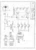
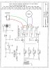
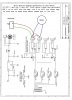
Hi, I'm trying to get a relay output board with 4 high current relays working with a BS2 or Atmel. I am fine with the micro-controllers, but don't completely understand this interface board. I ordred the board from Futurlec and it has limited documentation: https://www.futurlec.com/Relay_4.shtml
I'm wondering if anyone has used this and could give me a suggestion for the hookup?
thanks so much! I know this is a super novice question..
I'm wondering if anyone has used this and could give me a suggestion for the hookup?
thanks so much! I know this is a super novice question..