Continue to Site

Welcome to our site!

Electro Tech is an online community (with over 170,000 members) who enjoy talking about and building electronic circuits, projects and gadgets. To participate you need to register. Registration is free. Click here to register now.

  • Welcome to our site! Electro Tech is an online community (with over 170,000 members) who enjoy talking about and building electronic circuits, projects and gadgets. To participate you need to register. Registration is free. Click here to register now.

Relay controlled by LM555

Status
Not open for further replies.

GJS

New Member
hello,

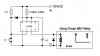
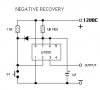
i've built a timing circuit using the LM555 (attached) and would like to use the control output (pin 3) to open/close a relay with a load of 120VAC (80mA). powering the LM555 circuit with 12VDC and the switch closed i get about 10VDC at pin 3 without anything connected.
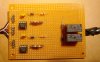
i have a few LCA110 and they can handle switching the lite load but i'm not sure how to connect them. i don't think i can drive the relay directly with pin 3.

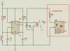
how can i use an LCA110 with my LM555 circuit?

thanks and GREAT forum!
 

Attachments

  • LM555cir2.jpg
    LM555cir2.jpg
    45.1 KB · Views: 1,156
The input of the LCA110 is a diode, so all you need is a resistor to limit the current. 20ma should be fine, so if your 555 circuit puts out 10 volts, you need a 500 ohm resistor inline to the +control line on the LCA and the -control line on the LCA is grounded. The output of the LCA is wired according to the data sheet.
 
thank you Sceadwian. it worked perfectly!

for anyone interested...
i wanted to experiment with switching more of a load so i used my LM555 circuit to control an 892 relay. unlike the solid state LCA110 the 892 has a coil that has a resistance of about 210 Ohms and needs about 40 mA to activate at 10VDC. i removed the current-limiting in-line 500 Ohm resistor and connected the output pin 3 of the LM555 directly to one side of the coil in the 892. it works just as i want and the 892 can switch loads up to 7 Amps at 125 VAC in the normally open configuration.
 
I hope you put a diode across the col to prevent frying the 555 or ?? due to coil flux.
 
Yes, the flyback diode is very important on the primary of the coil to make sure the circuit survives. It's connected in the opposite direction of current flow across the primary coils leads, when the 555 turns off the magnetic field in the primary coil collapses and will generate a current, if there's no path for that current to flow through it will generate voltage until the current can flow, which can be lethal to the 555. The diode will be reverse biased when the relay is switched on and when the coils collapsing field generates a reverse voltage it will flow through the diode and dissipate in the coils resistance, preventing high voltages from being generated.
 
but what? A diode used that way has several different names, I tend to call them flyback diodes although for their use calling them freewheeling diodes may seem more right to some people. I've heard them called snubber diodes, catch diodes, and just generically protection diodes as well.
 
I've been testing my circuit (attachments) and I'm occasionally getting some odd behavior.
Usually when S1 is opened a short delay occurs and then the relay opens. However, sometimes when S1 is opened I notice the time delay pass and I hear the relay *click* but it has just momentarily opened and then closed again even though S1 is open. If I measure the LM555 output (pin 3) I see the voltage drop for a split-second after the delay but it goes high again even though S1 is open. This happens about one out of ten times when S1 opens. When the relay doesn't open as expected usually only one extra delay interval passes and then the relay *clicks* open but sometimes a few delays can pass with S1 open and the relay just momentarily opening each time interval which leaves the load running.

I only get this behavior when the relay is switching a load drawing current. Without a load, when I test pin 3 or continuity between the relay outputs, I get what I would expect: S1 opens, after a delay pin 3 goes low (and remains low) and the relay opens. I cannot repeat the odd behavior without a load.

I thought the current the load was drawing could have been causing a problem so when I built two of these circuits on a perf board (attached) I tried to keep the relays away from the rest of the circuit. Unfortunately both circuits exhibit this problem.
The loads draws about 500-800 mA.


Why does the LM555 pin 3 sometimes remain high even though S1 is open?

Are there any other improvements (shielding?) you can suggest that might help?


Thanks!
 

Attachments

  • simpleton-LM555cir3.jpg
    simpleton-LM555cir3.jpg
    48.5 KB · Views: 663
  • simpleton-LM555cir3a.jpg
    simpleton-LM555cir3a.jpg
    129.9 KB · Views: 703
  • simpleton-LM555cir3b.jpg
    simpleton-LM555cir3b.jpg
    163.1 KB · Views: 463
May be a snubber network across the relay contacts will solve the problem. Do you supply resistive or inductive loads via the relay?
 
The datasheet for the LM555 describes two supply bypass capacitors that are are needed.
The datasheet for the ICM7555 Cmos 555 describes a 400mA supply current spike that occurs when the output of an ordinary 555 switches that might starve the 555 if it doesn't have supply bypass capacitors to keep the supply voltage from dropping too low during the spike.
 
Last edited:
Do what Audioguru suggests: 100nF capacitor from Pin5 to Pin1 (short leads) 10uF capacitor (+ to pin 8, - to pin 1)
 
Thanks for your help.

I've added the capacitors but I'm still getting the same behavior.

Any other ideas?
 
Last edited:
What are you powering the 555 from? Is it the same power supply as powers the Pump? How are the wires routed? Provide a system diagram
 
I've tried a few power supplies. Two Radio Shack AC to DC 12V (500mA, 1500mA) and a 12VDC (1A) switching power supply.
Here's how it's set up:
241-simpleton-pumpcircuit.jpg
 
Ok, I see that you are powering the pump off the same supply as the 555. Here is what I think is happening. During start-up the pump draws more current than any supply you have tried so far can deliver, so the voltage sags momentarily while the pump motor accelerates.

Try this. Get a 1N4001-1n4007 or 1n5817 diode. Connect it in the +12V line pointing at the 555. Leave the pump connected directly to the supply (so the pump current does not flow through the diode). Increase the size of the capacitor tied between pins 8 and 1 to 470uF or larger. This should store enough energy to supply the 555 and relay while the pump comes up to speed.
 
Thanks for your help. I really appreciate it.

The problem I'm having is getting the darn pump to turn off. The pump comes on as expected.
I'm trying to use my circuit to turn off the pump when the tank is empty. The functionality I'm trying to get is: switch (S1) opens and after a short delay the relay returns to "normally open" and the pump stops. The circuit now sometimes leaves the relay closed (pump on) after S1 has opened.
It must have something to do with the load current because I can't make the circuit fail without the load. I'm stumped.
 
Maybe the timing capacitor has too much leakage current so it does not charge high enough for pin 6 to detect it and cause the output to go low.
Maybe the 555 is defective.
 
Another reason might be the floating reset pin (4) of the timer.

Connect it to +12V and omit the diode between pin7 and pin2.

I don't see what it should do. Pin2 is pulled up by a 10K resistor anyway.

Also try to supply the pump off another wall outlet.

Boncuk
 

Attachments

  • MONO.gif
    MONO.gif
    12.5 KB · Views: 728
Status
Not open for further replies.

New Articles From Microcontroller Tips

Back
Top