Continue to Site

Welcome to our site!

Electro Tech is an online community (with over 170,000 members) who enjoy talking about and building electronic circuits, projects and gadgets. To participate you need to register. Registration is free. Click here to register now.

  • Welcome to our site! Electro Tech is an online community (with over 170,000 members) who enjoy talking about and building electronic circuits, projects and gadgets. To participate you need to register. Registration is free. Click here to register now.

Relay connection

Status
Not open for further replies.

Christy

New Member
Morning,afternoon or evening,whatever the time zone is.
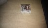
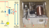
I need some help,I haven't used a relay before and would like to know if someone could help on how to connect the relay of the image i uploaded to the same configuration as the circuit it's being used in, i also uploaded the circuit diagram pdf document.I could not find the datasheet to help me figure it out.The name is ITALIANA RELE' 12Vdc 10A.
The help would be appreciated.
Thanks.
 

Attachments

  • IMAG0216.jpg
    IMAG0216.jpg
    898.2 KB · Views: 202
  • battery_charger_indicatorCI-01_Dec08.pdf
    176.1 KB · Views: 214
It looks like a SPST relay. Check out this link. The two pins on the right likely go to the coil and the two pins on the left to the contacts. I'm not sure if 12VDC 10A is the contact rating or if 12V is the coil voltage and 10A the contact rating. Probably the first one if I had to guess. If you're unsure about the coil voltage just start with a low voltage and gradually increase it until the relay closes. You should be able to hear it when that happens. As far as how to hook it up to your circuit. Look at the attached picture. That's what I'd try first.

EDIT: I didn't notice when I glanced at the picture the first time that there appears to be a third pin on the left side of the relay. If that is indeed a third pin then the relay is likely SPDT with one NC (normally closed) contact, one NO (normally open) contact, and one COM (common). If they are not marked, to find out which one is which you'll need a multimeter and a high enough voltage to actuate the relay. Take your multimeter with no voltage applied to the coil and of the 3 pins on the left, test for continuity between 2 pins at a time. When you find which pins have continuity, one of those pins is the NC pin and one is the COM pin. Next, apply a high enough voltage to the coil to actuate the relay and test for continuity again. Which ever pin had continuity when the coil was both powered and un-powered is the COM pin. The other is the NO pin. Lastly, you can unpower the relay.

I updated the pic to show what I'm talking about. I don't know if I identified the NC, NO, and COM pins correctly. The picture is just an example. You'll have to verify which pin is which through the method I described above.
 

Attachments

  • relay.PNG
    relay.PNG
    265.6 KB · Views: 211
Last edited:
Thanks for the reply VNE.will give it a try and if I do have a problem,will post it on this thread.Thanks a lot..
 
This data sheet may help Finding the company is easy and they can be found here so if you have the part number off the case it should turn up. I believe vne147 pretty much has it covered. You should be able to see the pinout through the plastic case.

Ron
 
thanks for the datasheet Ron....could you help me also on how to connect the pins according to the circuit i uploaded.
 
VNE,Ron helped with the datasheet of what the pins look like,could you please help what to connect where.I'm a student and know little about relays.thanks
 
VNE,Ron helped with the datasheet of what the pins look like,could you please help what to connect where.I'm a student and know little about relays.thanks

If that is indeed the correct datasheet for the relay you've got then pin 3 is NC, pin 4 is NO and pin 5 is COM. I have updated the picture accordingly.
 

Attachments

  • relay.PNG
    relay.PNG
    309.2 KB · Views: 170
thanks vne,i have tested for continuity,there is continuity between 3 and 5 when the relay was not supplied with voltage.
 
In the drawing VNE provided the Hot or Live runs through the relay as drawn and the mains neutral is on the right. The relay is switching the mains hot or live. Does that make sense?

Ron
 
thanks vne,i have tested for continuity,there is continuity between 3 and 5 when the relay was not supplied with voltage.

That confirms the picture is probably correct. 3 = NC, 4 = NO, and 5 = COM. To be 100% you can apply a voltage to the coil and verify continuity between pins 5 and 4.

Also, be very careful when working with mains. They can kill you, literally. Don't take this the wrong way but you are asking some fairly basic questions. So, I worry a little about you playing with mains voltage.
 
Also, be very careful when working with mains. They can kill you, literally.

So, have you looked at your avatar lately? :)

Just had to..........

Ron
 
yip,makes perfect sense Ron,u always do, when u respond to my threads.thanks!

VNE did all the work. I simply demonstrarted that even blind squirrels find an ocasional acorn using Google. :)

Ron
 
haha.none taken.thats why i have also asked about which is live and neutral that is connected to the relay so i would'nt connect them the wrong way and injure or kill myself...what's the best advice can you give me when I'm dealing with AC mains voltage?
 
So, have you looked at your avatar lately? :)

Just had to..........

Ron

Haha! I know, right? Like I should talk. See Christy, I'm living proof of what can happen to someone who doesn't respect the Mains God.

Actually, I wish my avatar was me. It's this guy though:


haha.none taken.thats why i have also asked about which is live and neutral that is connected to the relay so i would'nt connect them the wrong way and injure or kill myself...what's the best advice can you give me when I'm dealing with AC mains voltage?

I'm sure there's someone out there with much better advice than this but I would say, check, double check, and then triple check your connections and always be sure. If you're not 100% sure or if there's any doubt in your mind that the connections might be wrong, don't do it and ask for help.
 
Last edited by a moderator:
wow this guy is amazing!by thank u vne for all your help,I reaaly appreciate it.Thanks for the advice too.thank u too Ron!till i have problems again,bye!
 
Hey Vne.I also have another circuit that uses the same relay but i was told the relay is connected wrong because it is creating a dead short on the ac mains.can u help on how to reconnect it properly? here is the wesbite of the circuit : **broken link removed**
i just would like to use the light bulb only and not with the fan as the circuit shows.
Thanks
 
Christy

That circuit is crap and has come up in these forums before. Yes, the relay configuration presents a dead short to AC mains and there are other circuit errors. There is absolutely no way that circuit could have ever been "tested" as they claim. I believe it was Mr. Eric Gibbs (a forum member) who actually reworked that circuit and produced a good working circuit to do what that circuit was supposed to do. There was an extensive thread on that circuit. Rest assured you do not want to build that mess. :)

Think about it, what exactly happens when I press the RESET button as the circuit is drawn? That is just a single example of several other problems.

Oh yes, also note the polarity of C2? Seems backwards to me, how about you? :)

Ron
 
Last edited:
Status
Not open for further replies.

Latest threads

New Articles From Microcontroller Tips

Back
Top