Electro Tech is an online community (with over 170,000 members) who enjoy talking about and building electronic circuits, projects and gadgets. To participate you need to register. Registration is free. Click here to register now.
Welcome to our site! Electro Tech is an online community (with over 170,000 members) who enjoy talking about and building electronic circuits, projects and gadgets. To participate you need to register. Registration is free. Click here to register now.
If we start this way nothing makes sense!
i tought it was relais...
ok then i will make another solution.
tss
Tks
i wanted to save one pin on the micro and only use one PWM signal to drive a motor controller wich will be used for a reverse
wanted to control te reverse light / fan (for the mosfets) from one relais..
You can do what you suggest but you need a better reason than saving a pin on your microprocessor. The only reason that I have encountered for doing this is when you have 12 Volt relay and a 12-24 Volt Power Supply. If the supply is 24Volts then a 50% duty cycle makes the average voltage across the coil 12 Volts. As your supply votage changes you increase the duty cycle to compensate.
This is a very specialized situation and I wouldn't want to do this on a routine basis.
some languages spell it relais - not sure the point of correcting some one.
I've seen another reason to PWM a relay coil - reduce the audible click. With a little experimentation, you can determine the pull in duty cycle and the click is reduced. the guy who did it actually create a pwm profile where pwm'd it fairly high for 10s of mS and then backed off while the contact "coasted" into place. He did an inverse profile for turn off. it was quite a bit quieter. this was for a piece of equipment that went into a library and they had completed the HW when the complaint about the clicking came up. A better solution would be an SSR but this solved the problem with out a redesign. pretty clever. I wouldn't do this for higher current relays since the slower pull in would increase the arc time.
As the language spoken on here is English (sort of?), there's no point in not correcting mistakes - bear in mind that even fluent english speakers may not know technical terms very well, it's unlikely that English classes in a non-english country would teach technical terms?. For that matter, english classes in England don't either!.
I imagine 'relais' is French?, just because it 'looks' French! - I did French at school (very poorly), but again we we didn't do technical terms.
Just checked with google translator, it's French for 'relay', may be Dutch as well?, they don't have a Dutch translator
Anyway, that doesn't really matter - I'm still not 100% sure what you're trying to do?, except it would be a lot more sensible to use an extra PIC pin to switch the relay for forward/reverse.
So to clarify, what you're hoping to do is have a single PWM output from a PIC driving a motor - as the PWM varies the motor speed varies. At the same time, you're wanting the same PWM signal to be fed to a relay circuit, presumably so if the PWM is under a certain value the motor goes forwards, and if it goes over that value the motor goes backwards?. Is that right?, and if so, what do you expect the speed of the motor to do?.
to keep the motor controller simple i wanted to use that pwm signal to drive the fets and to turn on one BC547c wich will ground the relais.
Sow when in reverse the lights goes on on the car and the fan starts blowing on the fetss..
now i have add some spare takeoff to the board sow now i have 3 pins free (its not that i don't have pins free its more that space islimited on the pcb..
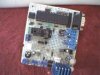
The picture is the gearbox board wich manages all the 3 servo's
- Accelerator
- Clutch
- Gearbox
as inputs it has:
- neutral switch bike gearbox (resets counter)
- Accelerator pedal
- Clutch pedal
as output it has also a Relais wich is normallu the clutch switch on the bike loom.
then you see a fet wich is spare to build one day a spark / injection interupt system in stead of servo throttle movement you see a 4pin to the steering wheel a 4min to the main pc for the gear display and errors..
You see the new 4screw block wich goes to the reverse controller board... you see a 1000uF capacitor, a 6volt regulator (3amps) and some normal ones and offcourse 5volts for the pic..
a memory socket (not in use yet) and a free 8pdip socket (not in use 2)..
a rs-232 takoff for debugging and for programing the brains of it..
This site uses cookies to help personalise content, tailor your experience and to keep you logged in if you register.
By continuing to use this site, you are consenting to our use of cookies.