Continue to Site

Welcome to our site!

Electro Tech is an online community (with over 170,000 members) who enjoy talking about and building electronic circuits, projects and gadgets. To participate you need to register. Registration is free. Click here to register now.

  • Welcome to our site! Electro Tech is an online community (with over 170,000 members) who enjoy talking about and building electronic circuits, projects and gadgets. To participate you need to register. Registration is free. Click here to register now.

Regulator Voltage Drop

Status
Not open for further replies.

ibwev

Member
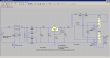
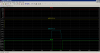
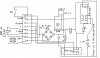
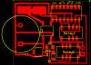
I assembled the attached circuit. I have at least one problem with the circuit. When I de-energize Relay 1 by opening the switch, the strobe led blinks once and then stops (if I connect a volt meter from output of regulator to negative of capacitor, the light will slowly blink). After the light blinks once, the voltage at the output of the regulator (LM317AEMP/NOPBCT-ND) reads about 3 volts. Prior to opening the switch, the output of the regulator reads 12.2 volts. The strobe light blinks steady and fast when I wire it directly to a 12 VDC power adapter. What is making the voltage regulator get stuck at 3 volts instead of maintaining the 12.2 volts it is suppose to yield?
 

Attachments

  • CircuitQuestion.png
    CircuitQuestion.png
    33.1 KB · Views: 195
  • CircuitQuestionPCB.png
    CircuitQuestionPCB.png
    16.7 KB · Views: 189
What I don't see is reversed biased diodes across your relay coils and I don't see the two small caps at the input and output if the regulator. These caps should be close to the regulator.

The regulator might be oscillating and the above mods has a chance of fixing that.

FWIW: In a commercial toxic gas alarm/shutdown system I put together with strobes and class 2 wiring with PTC protectors, all but two strobes worked. They were all from the same manufacturer. Turns out that the the ones that worked were "improved versions" with respect to inrush current.
 
Thank you for the help.

What I don't see is reversed biased diodes across your relay coils .
Is the attached file correct for the reversed biased diodes across the relay coil? Please explain the purpose of the reverse biased diodes.
 

Attachments

  • ReversedDiode.jpg
    ReversedDiode.jpg
    61.4 KB · Views: 167
yes, correct.

OK, the voltage across an inductor is v(t)= Ldi/dt. When you turn the relay off, di/dt is big and therefore the voltage created is BIG.

di/dt is mathematics for derivative. If you don't know calculus think of it as Δi/Δt; where Δt is small.

So, you want that spike to be absorbed by the relay coil and not elsewhere destroying drivers and playing havoc when the relay turns off.
 
A coil has energy stored in its inductance equal to 1/2 LI^2. When the coil circuit is interrupted the inductance will keep that current going until the inductive energy is dissipated. The diode provides a path for that current so the energy is dissipated in the coil and circuit resistance without damage. If the diode (or other path for the current is not available) then the inductive voltage will rise until an arc occurs or the relay coil switching device is zapped.
 
Your LED is shorted out when the lower relay coil is energised. I don't see how 7.5V can hold 9V relay coil.
 
Recheck LM317 pin out and connections.

I'm not sure what this circuit is supposed to do. Backup power maybe?
But anyway, I've redrawn the circuit and added a sim with the suggested changes.
Wasn't sure about the voltage rating for the relays so used 12v relays.

In the sim, the toggle switch closes at 500ms and is on for 100ms...

Shokjok was right on as the LED had no current limiter.
KISS also right on with diode snubbers.

eT:)
 

Attachments

  • AlarmCkt.png
    AlarmCkt.png
    28.2 KB · Views: 160
  • AlarmSim.png
    AlarmSim.png
    16 KB · Views: 150
Last edited:
Status
Not open for further replies.

Latest threads

New Articles From Microcontroller Tips

Back
Top