Continue to Site

Welcome to our site!

Electro Tech is an online community (with over 170,000 members) who enjoy talking about and building electronic circuits, projects and gadgets. To participate you need to register. Registration is free. Click here to register now.

  • Welcome to our site! Electro Tech is an online community (with over 170,000 members) who enjoy talking about and building electronic circuits, projects and gadgets. To participate you need to register. Registration is free. Click here to register now.

Regenerative receiver simulation

Status
Not open for further replies.

Elerion

Member
Hello everyone.

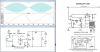
I'm trying to simulate a classic regenerative receiver under LTSpice.
I'm not sure if I'm doing things correctly.
I'd appreciate if anyone could correct me if I'm wrong, or suggets better ways of doing it.

I modeled the antenna as a voltage source.
Of course it is NOT real. I don't want a precise simulation. Just something OK to better understand the circuit.
The "tickler" coil is coupled to the tank circuit coil.

Thank you!
 

Attachments

  • regen.png
    regen.png
    339.1 KB · Views: 345
  • regen_1.asc
    2.3 KB · Views: 215
you may want to change V1 to something between 1 microvolt and 100 microvolts
 
you may want to change V1 to something between 1 microvolt and 100 microvolts
And make it a voltage source with a source impedance of ~100KΩ, or alternatively, make it a current source of a few uA.
 
you may want to change V1 to something between 1 microvolt and 100 microvolts

With such a small amplitude I'm not able to get any output.
The transistor never goes cuts-off, and the circuit stops demodulating the AM signal.

This is one reason why I suspect that I have done something wrong.
 
regenerative receivers are tricky to operate. you have to adjust the coupling between the tickler and the tank coil to where it barely begins to oscillate. you also seem to be missing the tank capacitor (the 200pf variable). first you need to find where the tank coil and the tank cap are resonant, and change V1 to that frequency, or find out what capacitance resonates the coil at 1 Mhz. once you have that, start playing with values of K in the mutual inductance statement. start with 0.1 and work your way up to 1.0 until you get the circuit barely oscillating. if you can't get it to oscillate, flip the phase of the tickler coil. a lot of regen receivers had the tickler mounted on a pivot so you could flip the tickler, and adjust it for oscillation, also, change V2's frequency to something closer to the middle of the audio spectrum, like 2Khz instead of 10khz
 
Last edited:
Status
Not open for further replies.

New Articles From Microcontroller Tips

Back
Top