Continue to Site

Welcome to our site!

Electro Tech is an online community (with over 170,000 members) who enjoy talking about and building electronic circuits, projects and gadgets. To participate you need to register. Registration is free. Click here to register now.

  • Welcome to our site! Electro Tech is an online community (with over 170,000 members) who enjoy talking about and building electronic circuits, projects and gadgets. To participate you need to register. Registration is free. Click here to register now.

rectifier identification

Status
Not open for further replies.

justin_t

New Member
hi
im trying to source a rectifier on a PCB im working on but it has very few markings.

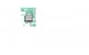
It is a surface mounted component approx 4.8 x 4 x 2.5 mm.

on the dc side there is a "+" and "-" for the terminal markings and between them is the number "6".

Below this and across the ac terminals is written "5.6G"

Im not sure if this is a standard component or if i have enough information but id like to use the same in the future if i can.

Also is there any other suppliers that are easy to use from the UK? im currently usinf Farnell and RS but they are limited for some components where id like a larger range.

Thanks

justin_t
 
How about posting a picture so we can see what you mean?
 
Here is a photo of the rectifier, its kinda upside down but as it is shown in the photo i think you should still be able to make out a "+" "6" and "-" to the bottom of the photo. (upside down so 6 looks like 9). and to the top of the photo the value "5.6G"

is this any help?
 

Attachments

  • untitled.JPG
    untitled.JPG
    22.2 KB · Views: 233
It looks fairly generic.

The markings on SMT components are often meaningless.

It looks like you'll have to guess.

Are you sure it's broken?

Or are you trying to revese engineer and build another one.

What does the module do?
 
Im trying to reverse engineer it, The rectifier is in a 5 VDC supply line fed from a 240 VAC to 9VAC transformer.
Its to supply and Atmel micro controller chip.

I guess ill just have to look around for something that does the same job with the same footprint. Thanks anyway.

Justin_t
 
Im trying to reverse engineer it, The rectifier is in a 5 VDC supply line fed from a 240 VAC to 9VAC transformer.
Its to supply and Atmel micro controller chip.

I guess ill just have to look around for something that does the same job with the same footprint. Thanks anyway.

Justin_t
hi,
From your description of the circuit, it sounds like a 50Vpiv 1Amp full wave bridge, get a rectifier with the same rating and PINOUT.

These are from Farnell. UK.
https://www.electro-tech-online.com/custompdfs/2008/08/dfs.pdf
 
Last edited:
I looked up the above rectifier but the dimensions/footprint arent the same.
How do i go about working out the current/voltage rating? is it normal to over spec? i.e. ive found a few with the same dimensions but the voltage rating are 140 + and the current ratings ar 0.5 A max output. should i be adding the current consumptions of each component on the board that is supplied by the rectifier (voltage regulator included)...

hi,
I would think if the rectifier is only supplying a MCU, its going to be rated at not more than 0.5Amp and as its connected to a 9V source, its rating is going to be no more than 50V
Any FWB that fits the 'footprint' and is rated at least 50Vpiv and 0.5A should be OK.:)
 
Last edited:
The main components on the board are as follows:
Atmel chip
7 segment display
12v buzzer
relay (12vdc coil)
Real time clock chip
there may also be an additional sensor that requires 200mA

Ive added up the current consumptions and they equal approx 0.404 amps.
I reckon 0.5 A rating should be enough. Ive found one on RS, same dimensions with 0.5 IFave but 400 VRRM, i think ill go for that one (RS625-7450)

Hi,
The 400Vpiv is well overated, but its not going to cause you a problem.
When running with the new FWB just do a couple of temperature checks on the body of the FWB.
From your calculations you have a 20% excess current overhead which should be OK.:)
 
Last edited:
Status
Not open for further replies.

New Articles From Microcontroller Tips

Back
Top