Continue to Site

Welcome to our site!

Electro Tech is an online community (with over 170,000 members) who enjoy talking about and building electronic circuits, projects and gadgets. To participate you need to register. Registration is free. Click here to register now.

  • Welcome to our site! Electro Tech is an online community (with over 170,000 members) who enjoy talking about and building electronic circuits, projects and gadgets. To participate you need to register. Registration is free. Click here to register now.

Recreating EC circuit

Status
Not open for further replies.

cyrusthevirus

New Member
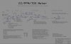
I am trying recreate a circuit I found online. The circuit is used to measure the electrical connectivity in a liquid. The circuit below also requires a probe and volt meter/pic to read the output. I have created a list of parts and just want to make sure I got them correct. The post I found online was from back in 2006 and my attempts to reach the person who created have been unsuccessful.

In addition to the parts below, What is D3? I believe it is a bridge rectifier. Can anyone suggest a part number or specs I should look for?

Finally from what I can tell the circuit appears to be fed by +12VDC and -12VDC. I plan to get this from a +12VDC circuit and a NJU7662 power inverter.

The specs are here:

https://media.digikey.com/pdf/Data%20Sheets/NJR%20PDFs/NJU7662.pdf


Here are the parts:

R1 1K (1/4W)
R2 1K (1/4W)
R3 56K (1/4W)
R4 33K (1/4W)
R5 100K (1/4W)
R6 1K (1/4W)
R7 6.8K (1/4W)
R8 22K (1/4W)
R9 1K (1/4W)
R10 220K (1/4W)
R11 220K (1/4W)
R12 220K (1/4W)
R13 100K (1/4W)
R14 100K (1/4W)
R15 82K (1/4W)

U1 TL074
V1 100K (trimmer resistor) (1/4W)
V2 2K (trimmer resistor) (1/4W)
V3 22K (trimmer resistor) (1/4W)

C1 .015uF (ceramic)
C2 .015uF (ceramic)
C3 .22uF (ceramic)

D1 In4733A
D2 In4733A

R200 3.9K (1/4W)
C200 10uF (ceramin)
D200 In4150
D201 IN4150
 

Attachments

  • Schematic..jpg
    Schematic..jpg
    513.9 KB · Views: 2,283
Yuck, I had to play around with that circuit in the Gimp to make it readable. I don't know why they didn't use a plain background, surely the CAD program has an option to turn the grid off.

Yes, D3 is just a bridge rectifier.

The power inverter IC might not be powerfull enough.

Are you powering this from a 12V mains power adaptor?

If so you could use an AC adaptor and a voltage doubler circuit to get +/- 12V.
 

Attachments

  • EC PPM TDS Meter..png
    EC PPM TDS Meter..png
    19 KB · Views: 3,333
Last edited:
Anyone? Here is a link to the original circuit discussion.

EC/TDS/PPM Meter

hi,
The D3 is a bridge, I would say, make up a full wave bridge for this project using 4 off, 1N914 or 1N4148 signal diodes.

As you say its powered by +/-12v
 
Last edited:
A note of caution!

On the very dotty circuit attached by cyrusthevirus, and the tidy version posted by Hero, there is a connection missing from pin9 of U1 to the bridge.
On the circuit in the original article, that connection is there.

There may be other oddities in the circuit as copied by cyrus, I did not notice any others, it is just that this one screamed out at me!

JimB
 
A note of caution!

On the very dotty circuit attached by cyrusthevirus, and the tidy version posted by Hero, there is a connection missing from pin9 of U1 to the bridge.
On the circuit in the original article, that connection is there.
Sorry, I can't see it.

On both circuits pin 9 is connected to the bridge.
 
Weird stuff going on here!

I had a look at the diagrams in this thread using another computer, perfect.

Looked again with this one, line missing.

Downloaded the file from its original site to this computer and displayed it using Windows Picture and FAX Viewer - perfect.

Look at the picture again in this thread - prefect. WHAT!!!!

Reboot this computer, look at the picture in the thread, line missing.

There seems to be something a bit odd about the video driver in this computer that is sorted by running Windows Picture and FAX Viewer.

As I said - WEIRD!

JimB
 
You need an AC adaptor (i.e. 12VAC, not 12VDC) in order for this to work.

It's only suitable for low currents, up to 50mA or so but that's enough for your circuit.

You might not need the regulators so you can omit them if they're not required. You can also save space by using the LM78L12 and 79L12 which are in TO-92 packages. Note that the pinout for the negative regulator is different to the positive, see the datasheets for more information.
 

Attachments

  • +-12V reg AC In..PNG
    +-12V reg AC In..PNG
    869 bytes · Views: 837
What do you mean? There is no R9.

The input is AC and the output is bipolar (both positive and negative) DC.
 
I couldn't see a VAC out anywhere - point it out to me.
 
It is obvious that the VACout signal is the attenuated sine-wave from the oscillator amplified by U1b.
The resistance between the probes controls the gain of U1b.
 
Last edited:
VACout is already connected in the circuit. It is for you to see what is going on.
 
Status
Not open for further replies.

Latest threads

New Articles From Microcontroller Tips

Back
Top