Voltz
New Member
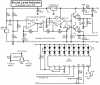
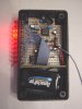
This is something I want to base a lot of my future projects on so I need to know this one, first I need a simple charger for a regular 1.2V Ni-MH Battery, (AA or D Cell), but I need it so that the charger can be disconnected from a jack and then the Battery begins doing the work... i.e. LED array, when the Battery is charging power comes from the Mains, when the Battery is not charging power comes from the Battery
So basically I need one circuit for charging the Battery (I've seen lots online but they look too obscenely complicated to be for a simple Ni-MH D/AA cell battery)
And one circuit for switching between mains and battery power
So basically I need one circuit for charging the Battery (I've seen lots online but they look too obscenely complicated to be for a simple Ni-MH D/AA cell battery)
And one circuit for switching between mains and battery power