Continue to Site

Welcome to our site!

Electro Tech is an online community (with over 170,000 members) who enjoy talking about and building electronic circuits, projects and gadgets. To participate you need to register. Registration is free. Click here to register now.

  • Welcome to our site! Electro Tech is an online community (with over 170,000 members) who enjoy talking about and building electronic circuits, projects and gadgets. To participate you need to register. Registration is free. Click here to register now.

Reading Volvo cooling fan schematic

Status
Not open for further replies.

jamyers

New Member
I've got a radiator cooling fan from an '01-'03 Volvo. I want to use it in an old Buick. The volvo fan has a speed controller mounted on it, but I don't know how it actually works - if it's a simple 12 signal, or a 5V square-wave, or what.

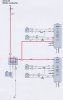
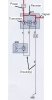
I've got the official Volvo wiring diagram (below), which matches up externally with the actual fan wiring I have. Red (A:1) power and Black
(A:2) ground leads going into the controller box (4/71), as well as a Violet signal wire (B:1) that comes from the ECM (either the ME7 or the Denso version depending on the car, but not both) Coming out of the controller box, straight to the fan motor are a White power (W) lead and a Black ground (CB) lead.

The ECM uses signals from various temp sensors (7/16 and 7/8), then tells the controller (4/71) what to do with the fan (6/29).

If I'm reading the schematic correctly, inside the controller (4/71) there's a resistor and transistors, and the idea is that the transistors are used to switch between three positions: Off, Low (via the resistor), and High.

My problem is that I can't figure out what kind of signal Volvo is passing through the signal wire to tell the controller what to do.

Any ideas on how I can control my fan speed?
 

Attachments

  • Volvo Fan Wiring.jpg
    Volvo Fan Wiring.jpg
    51 KB · Views: 1,772
  • VolvoFanWiring2.jpg
    VolvoFanWiring2.jpg
    41.9 KB · Views: 1,092
It looks very much like the Volvo controller is used on a Canbus network within the car.

Unless you have a lot of experience with Canbus communictions I'd explore another route.
 
Although looking at that diagram again 4/71 could be a simple power controller with the B:1 feed as a trigger.

If you're feeling adventurous then you could try applying a 5v feed through B:1 and see what happens. You could also try to borrow a portable scope to see what the signal along B:1 is when the fan is activated.
 
picbits said:
Although looking at that diagram again 4/71 could be a simple power controller with the B:1 feed as a trigger.

If you're feeling adventurous then you could try applying a 5v feed through B:1 and see what happens. You could also try to borrow a portable scope to see what the signal along B:1 is when the fan is activated.
I don't have a Volvo handy to put a scope on, although I've asked on some Volvo forums if anybody's interested - no takers yet. Wonder what response I'd get at a dealership, lol :eek:

I think I might try hooking up the power/ground leads to a 12V battery, then put 5V into the violet wire like you said (via a voltage divider). If that fails to do anything, bump it up to 12V. I figure the worst I can do is fry the controller box, in which case I'll cut it off and either run it in on/off mode or fab up a ballast resistor circuit to get a low-speed setting.
 
I'm with jumides that VO on speed controller 4/71 is an output instead of input.

The fan would switch ON automatically when temperature goes up.
 
If the violet wire (VO) is an output wire, then what makes the fan come on? Something inside the controller 4/71 that's not shown - like the "transistor-in-a-box" in the middle (what is that symbol anyway?)?

It'll be thursday before I can hook it up to anything - but I'm making a list of things to try. Thanks for the ideas so far! (jumides, your english is fine) :)
 
jamyers - I am glad you are trying to figure this out as I am inthe same situation with the same fan. Please keep me posted vis this forum on your testing results. I was talking to another car guy at work who has said that it might be possible that the normal condition is that the fan is on "LOW" and then runs faster depending on how hot the resistor gets. Seemed plausible, but I could not get any confirmation on that. I have read some things that would contradict that though. Please let me know how you made out.
 
When I get to work I'll look it up for you.


However, I'm 99.9% sure the wire from the ECU to the controller is a PWM signal to control fan speed. There would be no reason for the ECU to "know" if the fan is running.

I also wouldn't trust the "schematic" Volvo put on their wiring diagram that shows the internals of the fan controller. I often find manufacturers use "generic" schematics to show the internal workings of an electronic controller that have little to do with how they operate. Not sure why - maybe to keep technicians from prying inside?
 
Just checked. The ECU does send a PWM signal on the violet wire to the fan controller. However, it doesn't mention the voltage, freq or duty cycle.
 
volvo cooling fan controller module PWM

Hi,

Sorry for being a bit late ... there is interest from at least one Volvo owner: me. I seem to have problems with this module in my Volvo :(

According to specs, this control signal "A7" is supposed to be:
#A7 Engine cooling fan (FC) control signal
Pulse width modulation (PWM) signal, Uhigh=0.7*Ubat, Ulow =1.2V, F=100 Hz, Pulse ratio=10%-95%

See my post at
https://www.matthewsvolvosite.com/forums/viewtopic.php?f=11&t=24398
for more details. There are also some questions there, that I hope you could help me to answer.
 
Status
Not open for further replies.

Latest threads

New Articles From Microcontroller Tips

Back
Top