Continue to Site

Welcome to our site!

Electro Tech is an online community (with over 170,000 members) who enjoy talking about and building electronic circuits, projects and gadgets. To participate you need to register. Registration is free. Click here to register now.

  • Welcome to our site! Electro Tech is an online community (with over 170,000 members) who enjoy talking about and building electronic circuits, projects and gadgets. To participate you need to register. Registration is free. Click here to register now.

Reading 4 - 20 mA on LCD using PIC16F876A

Status
Not open for further replies.

aljamri

Member
My target is to use PIC16F876A to measure 4 - 20 mA and display it on LCD. Using Assembly or C.

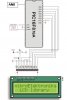
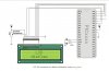
In my way to that, using MikroC for PIC ( Not the PRO), and while collecting the required Libraries, I’ve come to this ADC example, but found the code and the picture ( attached) are not matching …. Or am I missing something.

Code:
unsigned int temp_res;
void main() {
  ADCON1 = 0x80;  // Configure analog inputs and Vref
  TRISA  = 0xFF;  // PORTA is input
  TRISB  = 0x3F;  // Pins RB7, RB6 are outputs
  TRISC  = 0;     // PORTD is output
  do {
    temp_res = Adc_Read(2); // Get results of AD conversion
    PORTC = temp_res;       // Send lower 8 bits to PORT C
    PORTB = temp_res >> 2;  // Send 2 most significant bits to RB7, RB6
  } while(1);
}
 

Attachments

  • 1.GIF
    1.GIF
    18.4 KB · Views: 2,836
Last edited:
hi aljamri,
You need a precision 250R resistor to terminate the 4 to 20mA signal to give 1V to 5V for the ADC input.

The LEDs for the output are on PORTC and D pins.
EDIT;
attached LTS asc
 

Attachments

  • Draft109.asc
    522 bytes · Views: 448
  • AAesp02.gif
    AAesp02.gif
    23.1 KB · Views: 658
Last edited:
Edit: Sorry, see the next post
 
Last edited:
so with the folowing code and the attached circuit I can get indication for 4 - 20 mA ( 1 to 5 V) ?

Code:
unsigned int temp_res;
void main() {
ADCON1 = 0x80; // Configure analog inputs and Vref
TRISA = 0xFF; // PORTA is input
TRISB = 0x3F; // Pins RB7, RB6 are outputs
TRISC = 0; // PORTD is output
do {
temp_res = Adc_Read(2); // Get results of AD conversion
PORTC = temp_res; // Send lower 8 bits to PORT C
PORTB = temp_res >> 2; // Send 2 most significant bits to RB7, RB6
} while(1);
}
 

Attachments

  • 2.GIF
    2.GIF
    20.5 KB · Views: 802
hi,
It looks OK, the display will be 10 bit binary value of the adc input
 
Then, I'll try to adapt the same code and circuit to do this using 16F876A using MikroC and its Library. I'll use NG analogue Tutorial as a reference for the sequence.

Thank you Eric.
 
hi,
You could remove the bottom end +1V offset in the program, give you a Span of 4V.
 
hi,
You could remove the bottom end +1V offset in the program, give you a Span of 4V.

Software? or hardware shift?


EDIT: Thankyou Eric For the LT Spice simulation, I've got a question about the graph, I'll come to that later in my other thread.
 
Last edited:
hi,
I would do it in software, its cheaper and 4V is good enough.:)
 
I’m trying to under stand the steps of this routine,
Code:
unsigned int temp_res;
void main() {
  TRISA  = 0xFF;            // PORTA is input
  TRISB  = 0x3F;            // Pins RB7, RB6 are outputs
  TRISC  = 0x00;            // PORTC is output
  ADCON1 = 0x80;            // Configure analog inputs and Vref
  ADCON0 = 0x81;            //
  do {
    temp_res = Adc_Read(2); // Get results of AD conversion
    PORTC = temp_res;       // Send lower 8 bits to PORT C
    PORTB = temp_res >> 2;  // Send 2 most significant bits to RB7, RB6
  } while(1);
and if required to adjust it to work on PIC16F876A. Here is my view,

First set the ports up as follows:
PORTA as input : TRISA = 0xFF;
PORTB bit 6 and 7 as output : TRISB = 0xC0;
PORTC as output : TRISC = 0x00;

ADCON1 = 0x80; or b’10000000’
Bit7 (ADFM): A/D Result format select = 1 which means it is Right justified. (6 MSB of ADRESH are read as ‘0’

The least four bits of ADCON1 sets the analog inputs and the Vref, I set them as ‘0000’ which sets all PORTA bits into analogue inputs and makes the Vref+ = VDD and Vref- = VSS.

ADCON0 = 0x81; or b’10000001’
Bit 7 and 6 :A/D conversion Clock Selest bits, set as ‘10’, which = Fosc/32.
The next three bits 5,4,&3, are Analog Channel Select bits and set as ‘000’, which means channel 0 is selected, connected to pin (RA0/AN0).
Bit2: GO/DONE: A/D Conversion Status bit. If ADON (bit 0)=1 and it is, bit2 if s set (=1), starts the A/D conversion, so I made it = 0.
Bit0: ADON: A/D On bit is set (=1), which means A/D is operating.

After the setup, the main loop of the program,
do {

starts by Reading ADC, ( temp_res = Adc_Read(2))

then putting the ADRESH into PORTC, ( PORTC = temp_res; )

and ADRESL into PORTB ( PORTB = temp_res >> 2; )

} while(1); to keep on looping.

}

Any thing to be adjust ?
 
Last edited:
On the them chips i would change to AN0 and not AN2

temp_res = Adc_Read(0) If your going to use the MiKroC ADC library
 
Last edited:
Hi be80be,

Aha, that's one thing I've not noticed.

Secondly, I'm using MikroC but no PRO version, is it ok or shall I add anything ?

Thank you
 
The chip your using are what I call ADC dependent meaning if you use AN2 your also setting AN0 and AN1 to Analog.

In this case to get AN2 your setting a lot of pins to Analog. But if you change to AN0 it will more then likely work as planed .
 
Here you something to play with

Code:
// LCD module connections
sbit LCD_RS at RB4_bit;
sbit LCD_EN at RB5_bit;
sbit LCD_D4 at RB0_bit;
sbit LCD_D5 at RB1_bit;
sbit LCD_D6 at RB2_bit;
sbit LCD_D7 at RB3_bit;

sbit LCD_RS_Direction at TRISB4_bit;
sbit LCD_EN_Direction at TRISB5_bit;
sbit LCD_D4_Direction at TRISB0_bit;
sbit LCD_D5_Direction at TRISB1_bit;
sbit LCD_D6_Direction at TRISB2_bit;
sbit LCD_D7_Direction at TRISB3_bit;
// End LCD module connections

 char message1[] = "ADC Value= ";

 char *value = "0000";

 unsigned int ADC_Value;

void main() {
  ADCON0 = 0b11000000;
  ADCON1 = 0b10001111;
  TRISA  = 0xFF;              // PORTA is input
  TRISB  = 0;                 // PORTB is output
  Lcd_Init();                 // Initialize LCD
  ADC_Init();                 //Initialize ADC

  do {
       adc_value = ADC_Read(0);

   value[0] = adc_value/1000 + 48; // Add 48 to get character value

   value[1] = (adc_value/100)%10 + 48;

   value[2] = (adc_value/10)%10 + 48;

   value[3] = adc_value%10 + 48;

   Lcd_Out(1,11,value);

   Delay_ms(2000);
  } while(1);
}
 

Attachments

  • My_ADC.jpg
    My_ADC.jpg
    34.8 KB · Views: 593
Last edited:
Thank you be80be for your effort, but I tried the code and could not get it compiled. My be you are using the latest MikroC (PRO), I'm using vesion 8.2.
 
I'm using 8.6 pro version I have 8.2 some where I'll dig it out and see whats the deal
 
This should work for you
Code:
 char message1[] = "ADC Value= ";

 char *value = "0000";

 unsigned int ADC_Value;

void main() {
  ADCON0 = 0b11000000;
  ADCON1 = 0b10001111;
  TRISA  = 0xFF;              // PORTA is input
  TRISB  = 0;                 // PORTB is output
  Lcd_Init(&PORTB);                 // Initialize LCD


  do {
       adc_value = ADC_Read(0);

   value[0] = adc_value/1000 + 48; // Add 48 to get character value

   value[1] = (adc_value/100)%10 + 48;

   value[2] = (adc_value/10)%10 + 48;

   value[3] = adc_value%10 + 48;

   Lcd_Out(1,11,value);

   Delay_ms(2000);
  } while(1);
}
 
I tried to do somthing using HELP files and got this:

Initializes LCD at port with pin settings you specify: parameters RS, EN, WR, D7 .. D4 need to be a combination of values 0–7 (e.g. 3,6,0,7,2,1,4). Example: Lcd_Config(&PORTD, 0, 1, 7, 5, 4, 3, 2); so I changed the pins according to your LCD module connections and got Lcd_Config(&PORTB, 4, 5, 6, 3, 2, 1, 0); where WR bit is not mintioned I put 6. Then it gets stuck with Lcd_Init(); where I add (&PORTB) in the beraket, but again it gets stuck with ADC_Init(); I could not help it.

EDIT: I wrote this before seeing your post. Sooooory
 
Last edited:
YES, it got compiled. I'll take my time to make the circuit and let you know the results.

Thank You be80be
 
Here how the LCD hooks up it not the same as the newer 8.6 it uses The high bits for data

Hook it up just like SCH and it should work Use AN0 for your adc input. The 8.2 doesn't use ADC_init you can only use adc_read

8_2-lcd-jpg.54401
 

Attachments

  • 8_2 LCD.jpg
    8_2 LCD.jpg
    45.2 KB · Views: 1,736
Last edited:
Status
Not open for further replies.

Latest threads

New Articles From Microcontroller Tips

Back
Top