Hi again! Can you tell me the height (in volts) of those high levels or, in another words, the length (in volts) of those rising edges?
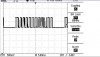
The problem is, as far I can see in that screenshot, it seems you have 0V for those low levels and not more than 0,5V in those high levels. If it is like that, the PIC will always read "0". That is why I'm asking. You need more than 2V to get a "1" in the RA1 pin. Also, could you attach a new screenshot where we could see the wave closer? A mean, I want to see the edges (the vertical lines) separatly. Maybe I'm complicating it too much. Do you also have any incoming clock signal at that transmission frecuency? You need to know when you have to read the pin again. I mean, how would you distinguish this signal: 0100011 from this one: 0101 or from this one: 000111000000000111111 if you didn't know when to read the pin again? You need a parallel "01010101010101" signal marking times.
I think 433 KHz maybe is not slow enough Vs 4 MHz to let the PIC read, store the value and read again each pulse. In another words:
A period of the RF trans lasts 1/433000 seconds= 2.3 us. A period of a PIC instruction lasts (the PIC needs 4 clock pulses to do one instruction) 1/[(1/4)*4000000]= 1/1000000= 1us. This means you receive new data from the RF module each 2.3us, and you have read the pin and store the data in 2.3 us I don't think this is time enough, because 2.3 us means 2 instructions in the PIC (if they are no goto, call or any jump instruction which last 2us). You have the option to change the XT crystal from 4MHz to 10 for example if your PIC supports it. Some 16F84A can, but not all of them. I think, even, there are some which support 20 MHz, but not sure. Have a look at the IC's reference in the chip itself. If there's something like "PIC16F84A-04" it means it'll only supports 4MHX clock frec.
Buuut, maybe all I've told you about this time problems is wrong know I see your scope screenshot again. You're transmitting at 433KHz. But the bitrate is quite slower. As I can see in the photo, in each box (5ms) you receive about 3 or 4 different bits) so, suppose you have 5 bits each box (even worse case) you would have 1 bit per ms= 1 bit to be red and stored in 1000us= 1 bit to read and store in a "1000 PIC instructions time", time more-than-enough to read, store, and get prepared to read again. So, in that case, your bit transmision frecuency would be 200 bits per second= 0.2 KHz. This is another world.
The almost impossible mission turns into a pretty possible mission. Now, you need to know when you start the transmision. If you do this, you'll be able to read, store and wait for the next time to read. Now, a question: Can you manage the bits you're sending and receiving? I ask this because you should add a little code at the beggining of each sequence to let the PIC know that the transmision starts in that moment.
Enough for today. If you are interested on that we can keep on thinking about how to make it. Cya!