Continue to Site

Welcome to our site!

Electro Tech is an online community (with over 170,000 members) who enjoy talking about and building electronic circuits, projects and gadgets. To participate you need to register. Registration is free. Click here to register now.

  • Welcome to our site! Electro Tech is an online community (with over 170,000 members) who enjoy talking about and building electronic circuits, projects and gadgets. To participate you need to register. Registration is free. Click here to register now.

Re: LED voltage display LM339

Status
Not open for further replies.

Gr3mlin2008

New Member
Hay ya all.
Im playing around with a display for the front of my PC, i've made an adjustable 3-12vdc circuit to control the speed of my fan on a server.
but i wanted to be able to see the output voltage on a led display type. so i looked around got some bits got 25% of the was through building it and stopped dead in my tracks.
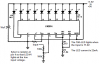
now, if im reading the simple circuit (link to follow) right, the adjusted voltage Vin is Neg.
the voltage circuit adjusts + not -
is there anyway to alter this circuit (link to follow) to monitor the Pos instead?

http://www.ecelab.com/circuit-simple-led-voltmeter.htm
 
The way I read the circuit when the positive input voltage exceeds the voltage on the + input of the particular comparator that particular comparator output goes low turning on it's LED. So the input voltage is + with respect to ground.
 
Instead of using that extremely old circuit, why not use an LM3914 LED voltage display driver IC? It has 10 comparators with all the divider resistors inside and has adjustable current outputs that are set with only one or two resistors. It drives up to 10 LEDs.
 
Instead of using that extremely old circuit, why not use an LM3914 LED voltage display driver IC? It has 10 comparators with all the divider resistors inside and has adjustable current outputs that are set with only one or two resistors. It drives up to 10 LEDs.

well, i shall get with the times then! :p lol, i tried to make my circuit, but it didnt really work. i sort of rushed..

So now i'll try a LM3914 circuit!
 
OK... what the... im completely confused now!
refin =/across 1-200%is at 1.23v vs 1.25v = r1-r4 within r2.
ok so i may not be as bad as that.. but im sitting here looking at the thing thinking.. wtf. it doesnt make any sense to me at all. i mean, it does, but it doesnt. and ... can someone just explain to me how on earth this all works?

I understand that the. im rather new to anything that has more than 2 legs. like honestly, i've only just started playing with transistors and using transistors!

how does one take a 2.5v - 11.8v adjusted voltage and turn it into a 0-1.25v signal.
im getting more and more grey hair here. is it simple and im just not getting it or is it really complex for a simple minded person like me.

The was my plan before started geting confused and bleeding from the ears.
I have a PC here thats a server, i've made the CPU fan run on around 5v, which is keeping it nice and cool, what i wanted to do is have to graphs, bar or dot, that part i do get! but basically one graph was going to tell me what the voltage is out from the fan speed controller, and the other was going to be the temp from the CPU.

SO that where i get stuck. well wait no i dont, i dont know where i get stuck, my brain just cant wrap my head around the IC.. its ticking me off...
 
The LM3914 has an adjustable voltage reference at its pin 7. Two resistors from pin 7 to pin 8 then to ground set the reference voltage to any voltage. The current in these two resistors set the LED current (brightness).
Set pin 7 to half of 11.8V (5.9V). Then connect pin 7 to pin 6 (the top of the resistor divider). Select a resistor from pin 4 to ground to set the voltage where the 1st LED lights.

Make an input divider to cut the input voltage in half.

The voltage is cut in half because the LM3914 will get too hot if its supply voltage is 12V.
 

Attachments

  • LM3914 voltmeter.PNG
    LM3914 voltmeter.PNG
    22.8 KB · Views: 13,203
So, firstly thanks everyone thats helped!
BUT i have another problem with it now.

I got it working perfect! then i made a PCB and i stuck everything onto it.

for sum weird reason i cant figure out. the 5th LED seems to light and stay on.
problem with that is the LM3914N is in bar mode not dot mode..
and no other LED's seem to light.
I have put 510R resistors between the output pin of the LM3914N and the LED, although i dont think this would matter, im still new to electronics.
Personal i think during the install of the IC onto the PCB its gotten a bit to hot and has cooked, so im going to get a ICsocket and another LM3914N and try that.
But has anyone else got any Ideas?
 
If the LM3914 gets too hot then it is destroyed.
You don't need resistors in series with each output to reduce the heat in the IC, you need just a single low value resistor in series with the positive supply to the LEDs then the resistor shares the heat. Then a 2.2uF or more capacitor must be used as a lower supply bypass capacitor at the LEDs, as shown in the datasheet.

In my Sound Level Indicator project I use a 10 ohms/1W resistor in series with the supply to the LEDs to reduce the heating of the LM3915. It has two LEDs in series at each output which also reduces the heating of the IC.
It has been running continuously for over 2.5 years without any problems (except its very old 9V rechargeable battery needed replacement).
 
Status
Not open for further replies.

Latest threads

New Articles From Microcontroller Tips

Back
Top