Continue to Site

Welcome to our site!

Electro Tech is an online community (with over 170,000 members) who enjoy talking about and building electronic circuits, projects and gadgets. To participate you need to register. Registration is free. Click here to register now.

  • Welcome to our site! Electro Tech is an online community (with over 170,000 members) who enjoy talking about and building electronic circuits, projects and gadgets. To participate you need to register. Registration is free. Click here to register now.

RC timer circuit not working...why

Status
Not open for further replies.

JohnL

New Member
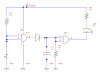
I am working through through Electronic Circuits for the Evil Genius. One exercise uses two NAND gates to turn on an LED. (I don't have a good way to include an image of the circuit, so I will describe it as best I can.) The inputs to the first gate are connected to 9V through R1 and to ground through a push-button. (So inputs will be HI until NO switch is closed). Output from first gate is connected through diode to inputs of second NAND gate and resistor/capacitor pair. So, when input to first gate goes LO, output goes HI and Input to second NAND gate is held high by voltage in capacitor until enough voltage drains through R2 that input to second NAND gate goes LO. At this point, LED's neg. lead is connected through second NAND gate to ground. (LED's positive lead is connected to V+.)

OK...my problem. When I close the NO switch, the LED comes on, like it is supposed to, but as soon as I release the switch, it goes out. The book says it should stay on for about 8 seconds (the time it takes for the voltage to drain from the capacitor through the resistor to half of V+ at which point state of NAND gate changes.)

Since the LED stays off when contact is open and goes on when contact is closed, it seems like the basic circuit is breadboarded correctly. But since the LED goes off immediately, it seems like the RC timer isn't working correctly.

How can I debug this? It seem so simple, but I can't figure it out.
 
My first guess, and without seeing the schematic it is only a guess, is that either the resistor (R2) or capacitor (C1) is too small of a value. What are you using for a NAND gate?
I would guess that the circuit looks something like this.
 

Attachments

  • mono4011.png
    mono4011.png
    6.4 KB · Views: 945
Last edited:
Your diagram is almost exactly what I'm working from. (I'm not sure why, but the current limiting resistor R3 is omitted. I believe that that may limit the life of the LED, but it shouldn't affect the rest of the circuit...unless it could burn out the 4011.) I have tried removing R2 which should eliminate the path for the voltage to drain...right? That should hold the input HI to the second NAND gate indefinitely ;-) and the LED should stay on, but it doesn't. ?????
 
I'm not sure why, but the current limiting resistor R3 is omitted.
The 4011 is not able to supply much current, so the LED is OK. The extra power is dissipated in the 4011, which is OK for just one output. I just add the resistor as a measure of "good practice".

I have tried removing R2 which should eliminate the path for the voltage to drain...right?
It should and the LED should then stay on for a very long time. The capacitor would slowly discharge due to self leakage. What is the value of the cap? ie: uF and voltage rating. Type of cap? Electrolytic? The cap isn't in backwards is it?
The diode, if it was shorted, could also be a problem. You could also have a bad 4011 with a input damaged by static discharge.
Could you post a picture of your circuit on the breadboard.
 
Photo of circuit.

Here is photo of my circuit.
 

Attachments

  • NAND Gate w RC timer.JPG
    NAND Gate w RC timer.JPG
    1.4 MB · Views: 1,180
It should work according to the photo.
The leads on the diode appear too thick for it to be a 1n4148 or 1n914. What is the part number on the diode?
 
The part no. is 1N4733A
That's your problem right there. That is a 5.1V, 1W zener diode. A 1N400x (Where x is any number between 1 & 7) would be better. If you have a 1n4148 or 1N914 I would use that.
Glad to help. :)
 
Last edited:
Thanks again...I replaced the zener diode w/ a 1n4005 and the circuit works. I had tried to test the previous diode thinking it must be bad, but it didn't occur to me that it could test good but still be inadequate. After re-reading the instructions I saw a footnote about the diode that I had missed previously.
 
Status
Not open for further replies.

Latest threads

New Articles From Microcontroller Tips

Back
Top