Electro Tech is an online community (with over 170,000 members) who enjoy talking about and building electronic circuits, projects and gadgets. To participate you need to register. Registration is free. Click here to register now.
Welcome to our site! Electro Tech is an online community (with over 170,000 members) who enjoy talking about and building electronic circuits, projects and gadgets. To participate you need to register. Registration is free. Click here to register now.
@Nigel Goodwin
hello Nigel Goodwin, i live in pakistan and they are not available here and if i get one, they would be at a pretty high prize. so i think it would be easy and cheap to build one rather than to fin and buy one. So can you please tell a link or video which tells me an easy way to build a servo.?
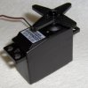
I doubt it. Most links that involve making servo electronics will require a servo's gearbox - you wouldn't be able to make a gearbox as strong and precise as a servo's without spending a LOT more than a servo costs.
I doubt it. Most links that involve making servo electronics will require a servo's gearbox - you wouldn't be able to make a gearbox as strong and precise as a servo's without spending a LOT more than a servo costs.
Servos are made inexpensively in many countries. They are sold in hobby stores for model airplanes, cars and boats. Why are they not available in Pakistan or why are they expensive there??
Servos are made inexpensively in many countries. They are sold in hobby stores for model airplanes, cars and boats. Why are they not available in Pakistan or why are they expensive there??
@audioguru
Although, you are right about Pakistan. But you know all five fingures are never equal so different kind of people live here But unfortunately unwanted people are larger in number. that is our bed luck.
@Boncuk
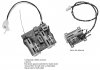
Thanks a lot for posting me the schmatic and Pcb. this is axectely what i was looking for.
now let me tell you the truth that i am build a small airplane and the body is almost ready. But can you guys tell a block diagram of electronics circuit used in it. please. like how Battery,radio circuitary connected and how servoes are connected.? mean how all the circuits are connected togather.?
building your own RC control takes about four to five times the investment you'd have to consider when buying a complete RC transmitter and receiver off the shelf.
You will need a transmitter using a common (license free) frequency in the 27, 40, 315, or 433MHz band emitting coded information for each servo you want to control. Those devices are commonly known as digital-proportional RC transmitters.
The transmitter sends a sync pulse for the receiver which starts counting up from zero.
Thereafter the transmitter sends steering commands of 1.0 to 2ms length (with 1.5ms being the neutral servo position) in sequence according to "channels". (one channel has double function, e.g. rudder right, left and neutral).
The steering commands are normally transmitted at a frequency of 100Hz.
The receiver sends the info to the dedicated servo making it rotate one or the other way. The built in potentiometer (has to have a mechanical link with the rudder lever) moves the servo to the desired position and makes the servo stop within the dead band provided by the circuitry within the servo electronics.
That game continues until you switch of battery power to either the transmitter or the receiver.
My suggestion: Find a complete RC set at "ebay". There are cheap offers of the "Futaba F14", a 7/14 channel transmitter and receiver.
My small RC airplanes and helicopter have a 6-channels 2.4GHz receiver board that has 2 servos on it, two electronic speed controllers for the main motor and for the tail rotor and a gyroscope. The receiver board measures 1 square inch and weighs almost nothing. The servo board for the ailerons measures about 1/2 square inch and weighs almost nothing.
The Piper Cub airplane weighs almost nothing (29 grams with battery), the P-51 Mustang airplane weighs almost nothing (35 grams with battery) and the mSR helicopter weighs almost nothing (28 grams with battery).
The Li-Po single-cell batteries are 3.4 grams for 125mAh and 4.1 grams for 160mAh. Each airplane flight is 10 minutes to 15 minutes long and is 5 minutes for the helicopter.
The Piper Cub flies about 10kmh to 20kmh and the P-51 Mustang flies up to 30kmh. The P-51 Mustang has enough power to climb vertically.
Hey! guys Thanks a lot.
actually i am NOT building the control system. i have all the system Except servoes. But i have to connect them togather. that's why i am asknig you guys to tell me a block diagram that how should i connect the whole circuitary and motors.?
my Radio Control system is a 3 channel control system. i want to use them as, a channel for alierons, one for elevator, and one channel for throtle.
The receiver should have an installation manual that explains how to connect the control system together.
We don't know which radio receiver and battery you have so we can't help you.
@ audioguru
i have got an old reciever and control system. But i will find a way to them. and i'll connent them togather.
1 last problem. my battery is 7.2v. can tell a circuit which can make it 12v.?
A 7.2V battery is a heavy old Ni-Cad or Ni-MH type. Modern RC airplanes use Li-po batteries that are lightweight and powerful.
I don't know why you need 12V but maybe you should use a 12V battery because a voltage boosting circuit wastes power by making heat.
I don't know what is your "control system". An RC receiver has "control system" decoding of the channels so a channel can drive its own servo.
An RC car has steering to turn left, right or go straight.
An RC airplane also has steering to turn left, right or go straight so it is the same as in an RC car.
An electric RC car has an electronic speed controller that is the same as in an RC airplane.
An electric RC airplane does not need the H-bridge of an electric RC car that allows it to go in reverse.
But the "control system" in an RC car does not have a channel for the elevator, ailerons or flaps of an RC airplane.
This site uses cookies to help personalise content, tailor your experience and to keep you logged in if you register.
By continuing to use this site, you are consenting to our use of cookies.