si_rcproject
New Member
Hi,
I'm a complete novice at electronics and have just started to build a remote control hovercraft.
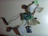
I'm using a ready made circuit taken from another RC product and that's going to provide the main body of the circuit. It has three 2.4V motors that can all be controlled seperately, with two of them being able to reverse direction.
However, this circuit only operates at 2.4V and I'd like to use it to operate 3 11V motors in the same fashion that the 3 2.4V motors work at the moment.
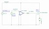
I was thinking of using transistors but the motor needs to be able to switch direction, and I haven't been able to find any relays that turn on at a voltage as low at around 2V. (porbably because I don't know what I'm looking for).
What would be the simplist way to make this work? Component codes would be great because I can't decifer what I need at the moment.
Thanks for any help.
I'm a complete novice at electronics and have just started to build a remote control hovercraft.
I'm using a ready made circuit taken from another RC product and that's going to provide the main body of the circuit. It has three 2.4V motors that can all be controlled seperately, with two of them being able to reverse direction.
However, this circuit only operates at 2.4V and I'd like to use it to operate 3 11V motors in the same fashion that the 3 2.4V motors work at the moment.
I was thinking of using transistors but the motor needs to be able to switch direction, and I haven't been able to find any relays that turn on at a voltage as low at around 2V. (porbably because I don't know what I'm looking for).
What would be the simplist way to make this work? Component codes would be great because I can't decifer what I need at the moment.
Thanks for any help.
 , other people's input would be useful.