Continue to Site

Welcome to our site!

Electro Tech is an online community (with over 170,000 members) who enjoy talking about and building electronic circuits, projects and gadgets. To participate you need to register. Registration is free. Click here to register now.

  • Welcome to our site! Electro Tech is an online community (with over 170,000 members) who enjoy talking about and building electronic circuits, projects and gadgets. To participate you need to register. Registration is free. Click here to register now.

RC Circuit Question

Status
Not open for further replies.

Madazadm

New Member
Hello,

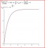
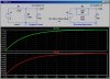
The attached image is the reduced RC circuit I've worked out, and i am wanting to sketch a graph of the output voltage over 5 time constants (note there was a switch open just before the first resistor near supply until t = 0, which then it closed). Capacitor initially fully discharged.

i worked out the time constant to be 0.55s (This is correct isn't it aha?) tau = RC = (110/110)k*10microF.

I know that at time t = 0, capacitor is initially full discharged and so the capacitor asks as a short circuit.

i also know that when the capacitor is fully charged (essentially at 5 times constants) it acts as an open circuit.

I think the main thing i'm getting confused about is what happens to the output voltage as there is a resistor in parallel with a wire.

If anyone could lend me a hand i would thoroughly appreciate it!

Cheers. RC.png
 
Hi.

Take a look at Thevenins theorem. It makes a lot easier to calculate the output.
 
Madazadm,

If anyone could lend me a hand i would thoroughly appreciate it!

As you can see from the circuit, at t=0 Vout also equals zero. It is also easy to see at t=∞, Vout will equal 3 volts.

This problem looks like a natural for node analysis. Since it has a capacitor in the circuit, we must set up a differential equation (DE) and solve. The attachment shows the DE written as a node equation and the solution. I also included a plot of the solution (Vout) which shows the capacitor just about completely energized in 2 seconds.

Ratch
 

Attachments

  • Madazadm.JPG
    Madazadm.JPG
    26.3 KB · Views: 234
...
i worked out the time constant to be 0.55s (This is correct isn't it aha?) tau = RC = (110/110)k*10microF...

Grossel's suggestion is spot on. You already recognized that per Thevenin, the two resistors are combined in parallel when figuring the time constant. Thevenin goes on to say that the voltage source should be reduced by the voltage divider action of the two resistors (R2/R1+R2)).

This confirms it:

Note that the two plots V(out1) and V(out2) are identical. V(out1) is the original circuit and V(out2) is the Thevenin Equiv.
 

Attachments

  • D3.jpg
    D3.jpg
    121 KB · Views: 243
Last edited:
Hi,


Here's a technique using source transformations that stem from Thevenin and Norton.

(See attachment)

In Figure 1 we have the original circuit.

In Figure 2 we have the voltage source and first resistor transformed into a current source.

In Figure 3 we have redrawn the circuit to show the two resistors side by side.

In Figure 4 we have the two resistors in parallel combined into one single resistor.

In Figure 5 we have transformed the current source and single resistor into a voltage source and single resistor.

In Figure 6 the voltage source voltage is simplified, and so we end up with a single resistor RC circuit. The circuit in Figure 6 is equivalent to the circuit in Figure 1.
 

Attachments

  • RC2.gif
    RC2.gif
    19.3 KB · Views: 239
Last edited:
Status
Not open for further replies.

Latest threads

Back
Top