Continue to Site

Welcome to our site!

Electro Tech is an online community (with over 170,000 members) who enjoy talking about and building electronic circuits, projects and gadgets. To participate you need to register. Registration is free. Click here to register now.

  • Welcome to our site! Electro Tech is an online community (with over 170,000 members) who enjoy talking about and building electronic circuits, projects and gadgets. To participate you need to register. Registration is free. Click here to register now.

RC car driven by induction ( help with college project)

Status
Not open for further replies.
Hi there!

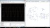
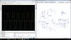
So I'm on my 5th year of college in the course of Electronics and Telecommunications, and I have this project that intends to use something similar to this:
So the thing we have to do is apply this concept to a regular RC toy car and make it run (without battery) on a designed track which countains the coils strategically placed, feeding the car's motor whenever it passes over them.

I'll be completely honest, I have no idea on how to approach this, and I was wondering if could get some guidance here.
Our teacher gave us some research work for next class but we weren't very successful on it...
He told us we would need to design an AC generator (functioning around some MHz-KHz) which may need a power amplifier to generate the magnetic field on the coils positioned on the track, which will consequently induce in the car's coils the necessary current to power on the motor and make it run. He also mentioned we could need a DC DC converter between the coils in the car and the motor, and that the most difficult part would be to figure out on to power the motor.

So there it is any suggestions on how to approach this?
(Sorry if I said some nonsense during my explanation, I'm far from being good at this)

Thanks in advance.
 
First of all thank you for your answer.
Could you briefly explain me how it works? I mean the Qi induction is supposed to charge batteries, since the car isn't supposed to have any batteries, I suppose the coils on the track will induce on the receiver and it powers the motor? I don't know. Sorry for the ignorance.
 
since the car isn't supposed to have any batteries
In that case you will have to rely on the car's inertia to move it from one coil position to the next, or else use some other means (electrical or mechanical) to store energy for such movement.
 
It looks like there are two options, coils in the "road" supplying the car as in the video you posted or a large coil in the car riding between parallel AC conductors, such as here: https://users.ece.cmu.edu/~vikramg/docs/hotemnets11.pdf
At first glance, the latter method will provide at most a mW or two, which is probably inadequate to run an RC car. Driving over embedded coils may be the only practical solution. Ultracapacitors might be considered a battery type (check with the professor). If so, I would consider a flywheel as an energy storage device to provide power between coils.

John
 
First of all thank you for your answer.
Could you briefly explain me how it works? I mean the Qi induction is supposed to charge batteries, since the car isn't supposed to have any batteries, I suppose the coils on the track will induce on the receiver and it powers the motor? I don't know. Sorry for the ignorance.
It would be nice to have a storage element as mentioned above, but not absolutely required. A capacitor might be acceptable.

Maybe we should ask how big is the motor and how long is the track?

The transmitter coil can be shaped to some extent if you build it yourself, but then things get complicated.
 
This is not too difficult, Except Your biggest Problem will be to get the Receive Coil in VERY CLOSE PROXIMITY to the Transmit Coil.
The Greater the DISTANCE Between these two coils, It Greatly Reduces Energy transfer Efficiency.
 
It would be nice to have a storage element as mentioned above, but not absolutely required. A capacitor might be acceptable.

Maybe we should ask how big is the motor and how long is the track?

The transmitter coil can be shaped to some extent if you build it yourself, but then things get complicated.

This will be our motor: https://www.sparkfun.com/products/11696
It has been checked by the professor as "enough for the task at hand".
The track is yet to be designed, the main goal is to get the car to actually move, the track format and length will come after.
And yes, we are supposed to design the coils ourselves.
 
What progress have you made?

John

We've designed the generator through an oscilating amp, also the power amplifier, and we are now trying to simulate the whole circuit on a software PSPICE, but we'll probably have to use AWR Mircrowave Office because of a particular power transistor model.

Our biggest problem lies on the coil design, because we have to guarantee enough current on them, so we've made some calculations on the number of turns, and diameter, and it seems to be right, but we're trying to simulate the circuit to confirm that it'll work.
The thing is, we never used these softwares to simulate something like this, it's not a regular transformer, it's 2 separate coils with some distance between them, far from an ideal circuit, we're trying to figure out how to do it right on the software...

I don't know if you guys are able to suggest anything further that may help, I would apreciate it, but I understand that now it gets more and more specific and hard to accompany.

Once again thank you all for your help.
You would probably get more help on this site if you use LtSpice. The transistors probably don't matter much to the simulation so you could just pick one that is similar.
The tricky part is estimating the coupling between the two coils. I've seen it stated at .3 to .6, but your spacing may be more than a typical charger.
Here is a link to one that may give you some ideas.
http://www.discovercircuits.com/dc-mag/Issue-1/issue-1-receiver-construction.htm
And some coils if you don't do your own.

http://www.mouser.com/Passive-Components/Inductors/Wireless-Charging-Coils/_/N-cbt1u/
 
Hello again guys, so I'm having this problem on my simulation with the receiver. The rectifier is putting the voltage to 0V, I'll show you the image with and without filtering.
On the left is the results and on the right is the circuit. I know this is PSPICE and not LTSPICE as previously mentioned, but if this is a circuit problem.
The images are attached to this post.

Does anyone know why this happens?

Thank you once again.
 

Attachments

  • 12250669_1070966089602707_805261234_o.jpg
    12250669_1070966089602707_805261234_o.jpg
    380.2 KB · Views: 154
  • 12255578_1070965679602748_1035833356_o.jpg
    12255578_1070965679602748_1035833356_o.jpg
    359.5 KB · Views: 157
What is the frequency?

1N4007 diodes do not work well at frequencies above a few 100Hz.

JimB
 
It look like the oscillator is running around 2MHz.
 
The small transistors cannot conduct enough current. Also they have no driver transistor.
Your schematic does not show the level of the input signal of V13 to the transmitter. It is a level that is MUCH too low since the transistors are emitter-followers with no voltage gain.
Your schematic also does not show where the 'scope is measuring.
The coils appear to be simply wire with no iron core.
 
Your schematic also does not show where the 'scope is measuring.
I believe the test point are indicated by the Small circle with the letter V inside. <---(V)
 
Then I see that the signal level is too low even for good high frequency rectifier diodes.
I wonder what is the transmitter signal level?
 
Status
Not open for further replies.

Latest threads

Back
Top