Electro Tech is an online community (with over 170,000 members) who enjoy talking about and building electronic circuits, projects and gadgets. To participate you need to register. Registration is free. Click here to register now.
Welcome to our site! Electro Tech is an online community (with over 170,000 members) who enjoy talking about and building electronic circuits, projects and gadgets. To participate you need to register. Registration is free. Click here to register now.
Use a meter and measure them, or simply read the values off them - a 5K may well be 4.7K, which is a preferred value (but they are fairly poor tolerance anyway).
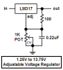
The circuit is wrong. With a 5k pot its voltage will try to go to 27V. If you use a 1k pot and replace the 240 ohm resistor with 120 ohms then its voltage will be 1.25V to 11.7V.
The LM317 will get hot and shut down if the load current and voltage across it are high.
That is not necessary jumper, just show that they are connected.
The dots are connections.
0.22 uF is 0.22 micro Farad capacitor
The aero is the variable resistor
Refer to the datasheet of LM317 for the calculation of the output voltage and the dropout voltage.
Correct me if I'm wrong but I take it you're a total electronics novice and you don't know what a resisistor, capacitor or integrated circuit is. If this is the case then you can read up on it a bit.
It's possible that the instruments might work from 6V but I don't know whether they will keep their accuracy. You could try buying a multivoltage car cigarette lighter adaptor and using it set to 6V or using the LM7806 regulator IC.
this is true, The only thing I can do as far as electronics goes is to follow a simple schematic that I can understand, lay out the components on a pcb, soldier them in and if the schematic is correct it will work, the main problem I have is that I dont know a 100 ohm resistor from a 200 by looking at it. same for pots and trimmers, the asst pack I purchased is not marked as I expected them to be.
The colour code for resistors is easy to learn.
Buy a $10.00 digital multimeter and measure the resistance of your unmarked pots. The multimeter will measure AC and DC voltages too. Don't measure current yet until you learn about how much damage too much current can do.
This site uses cookies to help personalise content, tailor your experience and to keep you logged in if you register.
By continuing to use this site, you are consenting to our use of cookies.