Continue to Site

Welcome to our site!

Electro Tech is an online community (with over 170,000 members) who enjoy talking about and building electronic circuits, projects and gadgets. To participate you need to register. Registration is free. Click here to register now.

  • Welcome to our site! Electro Tech is an online community (with over 170,000 members) who enjoy talking about and building electronic circuits, projects and gadgets. To participate you need to register. Registration is free. Click here to register now.

R meter

Status
Not open for further replies.

Adam2014

Member
Hi
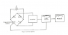
i want to design an ohm meter depending on Wheatstone Bridge (attached image given an example )
i know in general we measure the voltage between tow legs ...
Q1) what is the design steps ?
Q2) i read something like using ADC but why ?
i hope there are good designs and more information
thanks :)
 

Attachments

  • r.PNG
    r.PNG
    80.2 KB · Views: 165
i know pga309 just used for sensors like temperature sensors
it maybe helpful but it has a complex design !
 
i can use this design with (linearity error & gain control )
while V0=R1/R (E x) .... EQ(1)
what i have to do to measure resistance ?
-------------------------------------
an idea ::


if i want to measure the resistant between [1Ω , 1 megaΩ]
i can insert the minimum value in EQ(1) thus R=1
so V0=R1 E x ....EQ(2) and put it to (ADC - atmega MCU)
then i will measure R depending on any change in V0
but i want some help ...
how ADC work exactly , depending on its input and output?
how MCU can knowing if there is any change in V0
 

Attachments

  • rr - Copy.png
    rr - Copy.png
    54 KB · Views: 143
Last edited:
i can use this design with (linearity error & gain control )
while V0=R1/R (E x) .... EQ(1)
what i have to do to measure resistance ?
-------------------------------------
an idea ::
KeepItSimpleStupid said:
For some basic theory: https://www.google.com/url?sa=t&rct=j&q=&esrc=s&source=web&cd=3&ved=0CDIQFjAC&url=https://www.analog.com/static/imported-files/seminars_webcasts/49470200sscsect2.PDF&ei=dJsJVM7VOcrksASLkIDYBQ&usg=AFQjCNFjSrA67jjVQGRTwtdToEKNp6nOzQ&sig2=290Zlb0Te4cw9dt09UF80A&bvm=bv.74649129,d.cWc&cad=rja

if i want to measure the resistant between [1Ω , 1 megaΩ]
i can insert the minimum value in EQ(1) thus R=1
so V0=R1 E x ....EQ(2) and put it to (ADC - atmega MCU)
then i will measure R depending on any change in V0
but i want some help ...
how ADC work exactly , depending on its input and output?
how MCU can knowing if there is any change in V0
 

Attachments

  • rr - Copy.png
    rr - Copy.png
    54 KB · Views: 132
any help How does this circuit work ?
When op amp pin.11 = -Vcc the output is negative
else if it 0 the output is constant even if i change the unknown resistor value
 

Attachments

  • 3.jpg
    3.jpg
    115.6 KB · Views: 163
Sorry, it took a while to get back to you. Been busy and I had to think about my answer.

U1b essentially balances the bridge with some amount of current. The (voltage across RR)/RR. The current term probably drops out. In that circuit, to get a positive output, the unknown R has to be greater than 10K (10K+Ru)

Bridges can be voltage or current excited and they are very good at measuring small deviations from a standard value.

Not sure why you would want to use a bridge to measure such a wide range. There are better techniques such as 4 and 5 and 6 wire ohm measurement techniques. The 5 wire relys primarily on ratios and the 6 wire technique is a a way of compensating for leakage paths.

At low values of resistance, the lead and contact resistance swamp the measurement. Those contact resistances can easily be on the order of 500 mill-ohms. At the high end of resistance measurement, a zero resistance ammeter is used. The voltage drop can be much less than a mV and a 4-lead technique actually makes the measurement worse. Vos and the input bias currrent dominate. Vos is temperature dependent.
 
Hi
the attachment file shown my circuit design for ohmmeter ,,, it measure and work very well
but , i have one problem that is the output value is not a stable
for example if unknown resistor is 1 k ohm as shown the meter will display its value in a difference values like {995 ohm , 990 ohm , 1.20K , 1.10 K, ....}
what can i do to make the resistor value doesn't change a lot ???
R4,R5,R7 : the measurement scale .
i measure v1 using ADC then calculate Rx
 

Attachments

  • Rmeter.jpg
    Rmeter.jpg
    167.6 KB · Views: 139
My thoughts;

How is pin 5,7, 8 and 40 configured?

You seem to be using a rotary switch, but maybe your multiplexing the input. The top of Rx is the same point. Confused.

What are you using as a reference? I think you should be using V1 has a ratiometric external reference.

Not sure if you have to buffer an external reference.

What's your equation for resistance? I think it should be based on ratios and not an absolute number.
 
pin 5,7,8 related to selected resistance when it's low , pin 40 ADC input.
Vout= - Rx/(R4,5,7)*E where Vout negative so i measure v1 using ADC where V1=(E+Vout)/2
 
What I THINK you need to do, but I could be wrong is:
1. Buffer U1a, pin #2, call the buffer U1000
2. Connect a voltage divider between pin 2 and Vcc and make the center point within the normal range of the reference of the analog input.
3. Don;t know if the center point needs to be buffered or not. Depends on the input Z of AREF.

Rewrite the equations in terms of ratios. Your A/D would then be normalized to read a % of the voltage between the output of U1000 (zero volts) and Vcc. You may be able to use ground and Vcc.

it's just a thought anyway. Not sure how stable your voltage supply is. if it's from a switching regulator, it could be your problem because of the ripple. Doing the calculations ratiometricly would eliminate that.
 
Status
Not open for further replies.

Latest threads

New Articles From Microcontroller Tips

Back
Top