Electro Tech is an online community (with over 170,000 members) who enjoy talking about and building electronic circuits, projects and gadgets. To participate you need to register. Registration is free. Click here to register now.
Welcome to our site! Electro Tech is an online community (with over 170,000 members) who enjoy talking about and building electronic circuits, projects and gadgets. To participate you need to register. Registration is free. Click here to register now.
That's not the way a virtual ground is created. Please don't try to build this circuit. What is the purpose? The reason I ask is because virtual grounds are typically a by-product of certain op-amp configurations, and not something that's created for it's own usage.
You've confused things by slapping a ground symbol on the output - it's just to give a split supply from a single one, two resistors (and a capacitor) is usually all you need. The opamp is only needed if you have a poorly balanced circuit, and it should still have a capacitor as well.
Some of the confusion is that virtual ground can refer either to the minus input point in an inverting op amp, or to the pseudo-ground created to provide dual voltages for an op amp from a single supply.
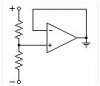
The op is obviously referring to the second use but his circuit makes no sense, with the resistors connected to plus and minus supply voltages and the op amp output grounded. The normal connection, of course, is the input resistors connected between the single supply and ground, with the op amp output being the virtual ground.
The + and - are the terminals of a single voltage source, e.g., a battery. Placing a ground symbol on the op amp output violates no rules. I've seen (and used) this configuration in the past. As Nigel pointed out, the op amp allows the loads (not shown) from + and - to GND to be unbalanced, up to the output current capability of the op amp.
This site uses cookies to help personalise content, tailor your experience and to keep you logged in if you register.
By continuing to use this site, you are consenting to our use of cookies.