Continue to Site

Welcome to our site!

Electro Tech is an online community (with over 170,000 members) who enjoy talking about and building electronic circuits, projects and gadgets. To participate you need to register. Registration is free. Click here to register now.

  • Welcome to our site! Electro Tech is an online community (with over 170,000 members) who enjoy talking about and building electronic circuits, projects and gadgets. To participate you need to register. Registration is free. Click here to register now.

questions about ideal transformer

Status
Not open for further replies.

Heidi

Member
Dear friends,

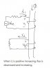
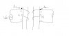
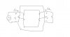
The two coils of wire in the drawing below represent an ideal transformer, assuming that it has a turns ratio of 10:1.
ideal transformer.JPG

When voltage source v1 is increasing from zero to its maximum value, the current i1 seems also to be positively increasing from zero to its maximum. During this time period, the resulting voltage v2 in the secondary coil seems to have a positive value that is increasing from zero to its maximum.
1. Is the voltage v2 the sum of mutual voltage and self-induced voltage?
2. Does the mutual voltage that is a result of increasing magnetic flux coming from the primary coil has a positive value? Does the self-induced voltage in coil 2 that is induced by the current i2 has a negative value, but the magnitude of the mutual voltage is larger than the self-induced voltage?

Thank you!
 
Last edited:
LTSpice models an ideal transformer. Note the primary current both with and without a load...
 

Attachments

  • D28a.jpg
    D28a.jpg
    308.6 KB · Views: 329
Thank you for your reply, Mike ML.

I'm not sure how to construct a schematic in an simulation program. I use PSpice.

It seems to me that in your circuit the secondary current i2 is in clockwise direction, and the secondary voltage and current are rising and falling at the same time, right?
 
When the transformer is loaded (switch closed), the primary voltage V(b), the primary current, same as I(R1), direction shown by the -->, The secondary voltage V(c), and the secondary current, same as I(R2), direction shown by the -->, are all in phase (resistive load dominates).

When the switch is open, the primary current, same as I(R1), direction shown by the -->, lags the primary voltage by 90deg. That is the magnetizing current, and is much smaller. It is purely inductive, hence the lagging phase.

Note that the turns ratio is √(Lp/Ls) = √(2000/20) = √(100) = 10. That is why the secondary voltage is 1/10 of the primary voltage.

I don't use PSpice, but I'm sure it has a transformer model...
 
Hi there Heidi,


I am editing this post :)
 
Last edited:
Hello, Mike ML

There is one thing I don't understand.

According to the voltage and current reference polarities in your model, should the primary voltage vb(t), the primary current i1(t), the secondary voltage vc(t) and the secondary current i2(t) have the following relationships, when the secondary circuit is loaded?

vb(t) = L1*(di1/dt) - M*(di2/dt)

vc(t) = -L2*(di2/dt) - M*(di1/dt), assuming L1, L2, M to be positive

But during the time period when both i1 and i2 are positive increasing, the secondary voltage vc(t) would be negative instead of positive. Where did I go wrong?
 
Last edited:
Hello, MrAl

I'm glad you mentioned the physical sonstruction and winding of the coils.

The downward flux through the core induces a positive current in the secondary winding (right hand rule again), ie the same current direction as the primary winding.
I thought the magnitude of the induced EMF in the secondary coil was equal to the change rate of the flux linkage through that coil, and the induced EMF would produce a current which in turn produced a magnetic flux to oppose the flux that caused the current in the secondary coil.
If the current i1 were positive increasing as shown in fig1 below, the magnetic flux would be also increasing and downward. At this moment, a induced voltage would be produced in coil 2 and hence the induced current i2 with their polarities as shown in fig1. But I DO NOT know whether this current i2 would be increasing or decreasing, and once there was a varied current i2 in coil 2, this i2 itself would produce a self-induced EMF in addition to the previous mutual-induced EMF, and I don't know which one would dominate. That's where I have stuck.
 

Attachments

  • fig1.jpg
    fig1.jpg
    26.1 KB · Views: 287
Last edited:
Neglecting magnetizing current, the increasing current in Coil 1 would be matched by the increasing current in Coil 2 (Coil 2 current actually controls the Coil 1 current) due to the flux coupling between Coil 1 and Coil 2. The relative voltages on the two coils are equal to their relative turns ratio. In an ideal transformer there is no self-induced EMF in the secondary, its EMF is determined by the primary EMF and the turns ratio.

Current does not produce EMF, it only produces magnetic flux. Thus the flux produced by the secondary current opposes the flux produced by the primary current. This leads to more primary current to maintain the required net flux in the core as determined by the input voltage rate-of-change. This is the method by which the secondary load current is reflected back to the primary.
 
Hello, MrAl

I'm glad you mentioned the physical sonstruction and winding of the coils.


I thought the magnitude of the induced EMF in the secondary coil was equal to the change rate of the flux linkage through that coil, and the induced EMF would produce a current which in turn produced a magnetic flux to oppose the flux that caused the current in the secondary coil.
If the current i1 were positive increasing as shown in fig1 below, the magnetic flux would be also increasing and downward. At this moment, a induced voltage would be produced in coil 2 and hence the induced current i2 with their polarities as shown in fig1. But I DO NOT know whether this current i2 would be increasing or decreasing, and once there was a varied current i2 in coil 2, this i2 itself would produce a self-induced EMF in addition to the previous mutual-induced EMF, and I don't know which one would dominate. That's where I have stuck.

Hi again,

The official equations look like this:

vp=-Np*dPhi/dt
vs=-Ns*dPhi/dt

and

vp/vs=Np/Ns

vp primary voltage
vs secondary voltage
Np primary turns
Ns secondary turns

Using these definitions if vp is increasing then vs is also increasing.

We could test this using a small core, some turns of wire, a frequency generator, and a two channel scope.
 
Thank you all. I think I need some time to think all your explanations over.

First,
In an ideal transformer there is no self-induced EMF in the secondary, its EMF is determined by the primary EMF and the turns ratio.
If the transformer in fig1 below represents an ideal one. For the choice of the voltage and current reference directions, do the following equations hold for this ideal transformer?

v1(t) = L1*(di1/dt) + M*(di2/dt)

v2(t) = L2*(di2/dt) + M*(di1/dt), assuming that L1, L2, M are all positive

If the secondary voltage v2 still had the above relationship with i1 and i2, wouldn't the term L2*(di2/dt) be the self-induced voltage in secondary coil?

Besides, if the current i2 in the secondary coil is varied with time, won't there be self-induced EMF produced in the coil?
 

Attachments

  • fig1.jpg
    fig1.jpg
    25.3 KB · Views: 298
Last edited:
Hello Heidi,


I cant figure out why you would want to draw your transformers with two separate *cores*. A transformer has one core and at least two *windings*.
Two separate cores are only weakly interacting and the orientation is not clear. So draw both coils on the same core so we can see what the polarities should be.
If the core is a toroid then draw two circles to represent the core. Or you could just draw two squares. If the windings are on the center leg of an EI type core, then you can get away with just drawing a single core if you like. But this is important for determining the direction of the flux in both windings.
 
........................

Besides, if the current i2 in the secondary coil is varied with time, won't there be self-induced EMF produced in the coil?
You are confusing cause and effect. The current in the secondary varies with time due to the flux generated by the primary, which generates the secondary voltage. There is no self-induced EMF.
 
You are confusing cause and effect. The current in the secondary varies with time due to the flux generated by the primary, which generates the secondary voltage. There is no self-induced EMF.

Thank you for your explanation, I really appreciate it.

There must be something I misunderstood.

This is just what I guess: whether the primary or the secondary voltage, is there a possibility that they are the final/ultimate results of corresponding mutual- and self-induced EMFs? Because the primary and the secondary currents are varying with time, I think they probably should have a self-induced EMF that they have to overcome, no matter what causes them?

Is this article saying the same idea?
https://farside.ph.utexas.edu/teaching/302l/lectures/node106.html

But this article says something I don't understand. Can this article represent what you are trying to explain to me, especially it says "At first, one might expect this secondary coil current to cause additional magnetic flux in the core. In fact, it does not. If more flux were induced in the core, it would cause more voltage to be induced voltage in the primary coil (remember that e = dΦ/dt). This cannot happen, because..."?
**broken link removed**
 
Hello Heidi,


I cant figure out why you would want to draw your transformers with two separate *cores*. A transformer has one core and at least two *windings*.
Two separate cores are only weakly interacting and the orientation is not clear. So draw both coils on the same core so we can see what the polarities should be.
If the core is a toroid then draw two circles to represent the core. Or you could just draw two squares. If the windings are on the center leg of an EI type core, then you can get away with just drawing a single core if you like. But this is important for determining the direction of the flux in both windings.

Sorry, I should have drawn two squares for the core. I was lazy :)
 
..............................................

But this article says something I don't understand. Can this article represent what you are trying to explain to me, especially it says "At first, one might expect this secondary coil current to cause additional magnetic flux in the core. In fact, it does not. If more flux were induced in the core, it would cause more voltage to be induced voltage in the primary coil (remember that e = dΦ/dt). This cannot happen, because..."?
That's a misleading statement. The secondary coil current does generate magnetic flux in the core but, since the current direction is opposite the primary current direction, the flux is also in the opposite direction and subtracts from the magnetizing flux generated by the primary. Thus the primary current has to increase to maintain the same core flux level. That is how an increase in secondary current causes an increase in primary current.
 
The secondary coil current does generate magnetic flux in the core but, since the current direction is opposite the primary current direction, the flux is also in the opposite direction and subtracts from the magnetizing flux generated by the primary. Thus the primary current has to increase to maintain the same core flux level. That is how an increase in secondary current causes an increase in primary current.
Hello, crutschow

I have another idea. Can I say that this is how an increase in secondary current in the negative current reference direction (referring to the secondary current reference direction in the figure attached) causes an increase in primary voltage, and that increase in primary voltage is to provide extra energy to overcome the production of the self-induced EMF, which is due to the increase of the secondary current in the negative current reference direction in the secondary coil?

Oops, there might be a contradiction. The primary voltage is a voltage source, it seems that it cannot be 'changed'. Hmmmm....
 

Attachments

  • fig2.jpg
    fig2.jpg
    25.4 KB · Views: 290
Last edited:
Hello again,


Well thanks for doing the core drawing over. That's much better.


Here's an expression for the output voltage (Ro is the load resistance):
Vout=(Ro*M)/sqrt((w*M^2-w*L1*L2)^2+Ro^2*L1^2)

and the phase shift is:
Phi=-atan2((Ro*M*(w*L1*L2-w*M^2))/((w*M^2-w*L1*L2)^2+Ro^2*L1^2),(Ro^2*L1*M)/((w*M^2-w*L1*L2)^2+Ro^2*L1^2))


For an ideal transformer, this simplifies to:
Vout=sqrt(L2/L1)

and

Phi=0

and of course these are both independent of the load Ro.


The initial voltage at the primary causes an increase in current which causes the flux to increase. The increasing flux generates a back emf in both windings of course.
 
I have another idea. Can I say that this is how an increase in secondary current in the negative current reference direction (referring to the secondary current reference direction in the figure attached) causes an increase in primary voltage, and that increase in primary voltage is to provide extra energy to overcome the production of the self-induced EMF, which is due to the increase of the secondary current in the negative current reference direction in the secondary coil?

Oops, there might be a contradiction. The primary voltage is a voltage source, it seems that it cannot be 'changed'. Hmmmm....
You rather have the polarity backwards. ;) You could say that application of a secondary current load causes an incremental reduction in the core magnetic flux. This causes an incremental reduction in the primary back EMF, causing the primary current to increase until the flux level is back up to the required value to give a back EMF equal to the primary voltage.
 
Status
Not open for further replies.

Latest threads

New Articles From Microcontroller Tips

Back
Top