Continue to Site

Welcome to our site!

Electro Tech is an online community (with over 170,000 members) who enjoy talking about and building electronic circuits, projects and gadgets. To participate you need to register. Registration is free. Click here to register now.

  • Welcome to our site! Electro Tech is an online community (with over 170,000 members) who enjoy talking about and building electronic circuits, projects and gadgets. To participate you need to register. Registration is free. Click here to register now.

Question on Voltage and power.

Status
Not open for further replies.

GilbertSam

New Member
Hi All,

I have one question here and really need all your help to answer this for my exercise question.

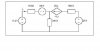
Please refer the attached file. Please explain how to find the voltage Vy and the power delivered or absorbed by the dependent source.

Appreciate a lot,

Regards,
Gilbert
 

Attachments

  • Question.JPG
    Question.JPG
    13.8 KB · Views: 194
Hey,
You have two independent variables here: the left loop current and the right loop current.
The current in the middle branch can be found using KCL.

All you have to do is writing down two KVL equations - one for the left loop and second for the right loop - and express all the voltages in each equation as a function of I_left_loop and I_right_loop.

Its all math from this point.
 
Last edited:
Hi alphacat,

Thanks for info. But I still in doubt on the extra independent source on the left and dependent source on the right loop. Headach.....

Please help.

Thanks & Regards,
Gilbert
 
Here is the answer; it is up to you to solve it algebraically.
 

Attachments

  • Meshc.gif
    Meshc.gif
    32.5 KB · Views: 177
  • Mesh.gif
    Mesh.gif
    8.4 KB · Views: 167
Hi alphacat,

Thanks for info. But I still in doubt on the extra independent source on the left and dependent source on the right loop. Headach.....

Please help.

Thanks & Regards,
Gilbert

Show the equations that you have derived, and then somebody can tell you where you went wrong (if you did).
 
Your answer seems to be a little off, MikeMI, because I(B1) has to be equal to I(R3), and that's not the case in your answer.

No, but it is close. In this case, I am using LTSpice to solve a system of simultaneous equations. I didn't bother to force it to go the few extra steps to get beyond about three significant figures...
 
Thanks MikeMI. Btw, I have tried to apply in Multisim but fail. As I know Multisim only able to simulate each result in one time. How SPICE can get all the result in one time as attached?

Really wonder how?

Really need your expertise on this. Please advice.

Thanks & Regards,
Gilbert
 
Thanks MikeMI. Btw, I have tried to apply in Multisim but fail. As I know Multisim only able to simulate each result in one time. How SPICE can get all the result in one time as attached?

Really wonder how?

Really need your expertise on this. Please advice.

Thanks & Regards,
Gilbert

Two things about the sim. First, notice I asked Spice to do a ".DC: simulation, not time domain, not frequency domain, etc. This type of analysis is similar to what it does to find the bias point prior to doing either a time domain (.TRAN) or freq domain (.AC) analysis.

Second, LTSpice (not sure other flavors of Spice know how to do this) has a magic "Behavioral Current source" called B that lets you express it's current as a function of a whole bunch of things, including, in this example, the current through the other mesh. I'm using the Behaviorial current source to get the network to converge on an approximation of the solution to two equations in two unknowns.

If your sim does not have a Behavioral Current source, here is an alternate way of using a sim to solve it. Sweep the current source until you find a current that causes Error = 29*I(R1) - I(R3) = 0.

I'm using the "waveform arithmetic" of LTSpice to plot the Error function vs I1 (the independent variable being swept by the .DC statement). By finding the value of I1 that causes the error function to go to zero, we have found the answer, namely 1mA and 29mA as the mesh currents.
 

Attachments

  • Mesha.gif
    Mesha.gif
    44.9 KB · Views: 149
Last edited:
GilbertSam, you said this is an exercise. Is the point of the exercise to solve the circuit with simulation, or to solve it by using a network solution method, such as the loop or nodal method?
 
Last edited:
As to how to solve this algebraically, I did it, and without showing you my work, I'll outline the approach.

First, you are told that the current in the right mesh I2 = 29 Ip.

Second, applying KCL to the common node, the current in the 200Ω resistor, I3 = Ip + I2 = Ip + 29Ip.

Third, applying KVL to the left mesh, the sum of the voltages is zero.

This is all you need to solve for Ip, and thereafter everything else falls out.
 
Not going to do your homework for you but this is a D.C. model for a bipolar transistor
 
Last edited:
Thanks All. I manage to solve it algebraically but only wonder on how to simulate through the useful tool such as SPICE and Multisim. On learning stage....

Thanks again.

Regards,
Gilbert
 
Status
Not open for further replies.

Latest threads

New Articles From Microcontroller Tips

Back
Top